Get in touch with Suzhou UDTECH Technology Co., Ltd. Company

CTO Activated Carbon Filter Cartridge Machine: A Process and Quality Guide

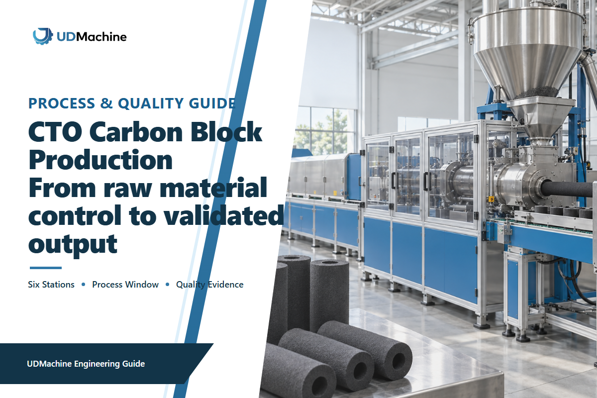
A CTO activated carbon filter cartridge machine uses activated carbon and binder to make a carbon block. A CTO activated carbon filter cartridge machine is the linked production line that meters, forms, cools, and cuts that blend. That’s a significant step, but it still doesn’t give us a qualified finished cartridge. Reduced chlorine levels, taste and odor control, pressure drop, structural integrity, and service life still require case-specific data.
Updated September 2026 · Written by Cherry · Reviewed for process and evidence boundaries
TL;DR
- Control the six linked stations as one system: mixing, feeding, extrusion, cooling, cutting, and dust collection.
- Freeze material identity and measurement methods before changing the process.
- Measure accepted pieces, not only nominal extrusion speed.
- Pressure drop with flow, geometry, conditioning, and test method should be read. It shouldn’t be interpreted as an adsorption or service-life signal.
- FAT and SAT should be used to validate an agreed product definition, evidence package, and restart rules.
What Does a CTO Activated Carbon Filter Cartridge Machine Make?
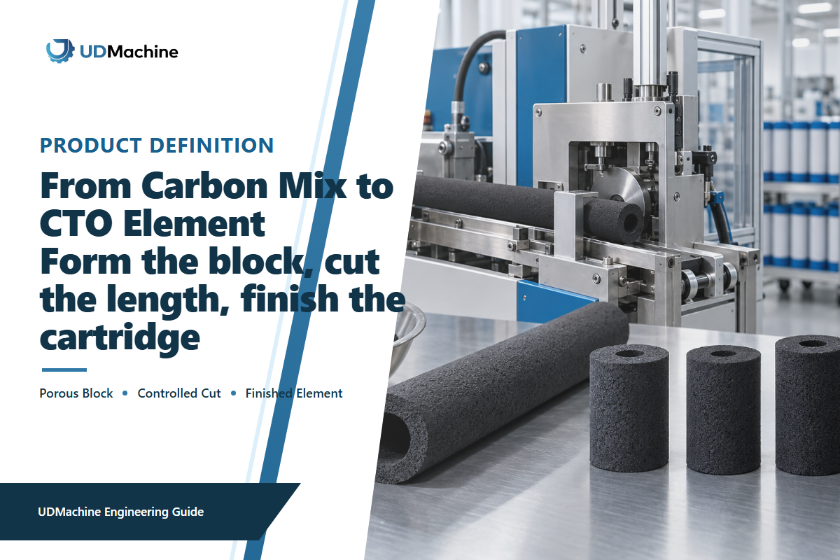
CTO usually refers to chlorine, taste, and odor controls for a formed carbon block. In the manufacturing process, the result is a physical block. The line measures and mixes raw materials, feeds the blend, forms a continuous profile, and stabilizes it through cooling and cutting to length. Nonwoven wrap, end caps, gaskets, labels, and packaging may be added in a separate downstream scope; the carbon block filter wrapping machine guide explains one of those later operations.
The names of equipment differ among supplier catalogs. The same process may be described as a CTO carbon block machine, a carbon block filter cartridge machine, an active carbon filter cartridge machine, CTO filter cartridge manufacturing, or an activated carbon block production process. In all cases, the end result is a formed filter element for a water filter cartridge. Throughout this document, I’ll refer to filter as the manufactured component, and not as evidence that the finished filter has satisfied a given treatment claim.
Search labels to separate before comparing a line
Supplier catalogs and search results group many related terms together. The following labels are useful for sorting inquiries, but they are not interchangeable specifications. For a broader map of equipment families, use the filter cartridge making machine hub and the filter cartridge making machine guide.
| Label group | Terms buyers may encounter | How to interpret them |
|---|---|---|
| Direct CTO line names | filter cartridge making, making machine, filter cartridge making machines, filter making machine, carbon filter cartridge making, CTO carbon block filter, CTO carbon block filter cartridge, CTO active carbon filter cartridge, CTO activated carbon block, CTO activated carbon block filter, activated carbon block filter cartridge, automatic CTO, full-automatic, filter machine, machinery | Treat these as search labels. Confirm the real process boundary, tooling, controls, utilities, and acceptance evidence before treating two offers as equivalent. |
| Media and formulation terms | carbon powder, activated carbon material, granular activated carbon, coconut shell, coconut shell activated carbon, PE, PP, carbon cartridge, high adsorption | These may describe an input, a claimed property, or a different cartridge construction. Each actual carbon-and-binder system needs its own trial window and evidence. |
| Adjacent cartridge machinery | PP filter cartridge, PP melt blown filter cartridge, melt blown filter cartridge machine, PP spun filter cartridge production, spun filter cartridge production line, winding filter cartridge machine, string wound filter cartridge machine, shower filter cartridge making machine, 2.5-inch formats | These equipment families can share a factory or downstream operations, but their forming mechanisms and process controls are not the same as CTO carbon-block extrusion. |
| Applications and sales claims | sediment, RO, contaminant, filtration efficiency, organic compounds, organic impurities, water purification, CTO water, household water, faucet, cyst, filtration solutions, industrial settings, low energy consumption, machine with CE certificate, CE certified | These terms describe possible contexts, product claims, or commercial attributes. None substitutes for a defined product test, energy basis, conformity file, or acceptance record. |
This helps avoid a common purchasing error. Even a straight, crack-free block can be acceptable as a machine trial sample while still lacking the evidence required for a treatment claim. According to NSF’s summary of drinking-water filtration standards, claims relating to chlorine, taste, and odor are product-specific and occur alongside material-safety and structural tests. The machine name, carbon grade, and micron label alone won’t suffice for those tests.
Please employ a two-step release: first, release the cut block against the agreed criteria for the machine-trial sample; second, release the completed cartridge against the specific qualification plan for the intended application.
Where line configuration, size range, level of automation, or commercial package is being considered, please refer to the CTO activated carbon filter cartridge machine solution page. This guide does not duplicate that commercial page; it focuses on process control, evidence, troubleshooting, and acceptance.
The Six Stations Work as One Production System
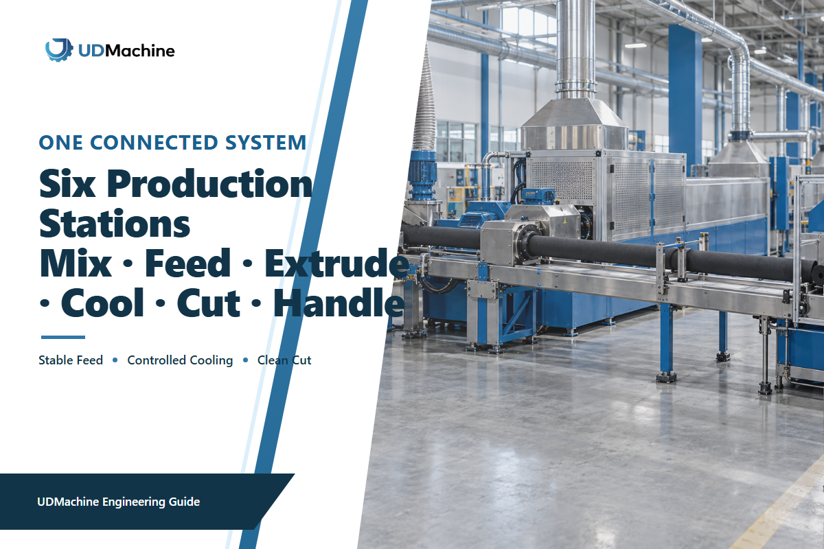
UDTECH publishes a six-stage sequence: automatic mixing, feeding, extrusion, cooling, automatic cutting, and dust collection. Each station has an input, an output, and a condition for the handoff. The filter production line solutions guide provides the wider line-planning context. A published extrusion patent treats feed uniformity, carbon and binder mesh, thermal input, and screw geometry as interacting variables, so no forming station should be assessed in isolation. Even a stable extruder won’t rescue a segregated blend, and an adequate profile can still be ruined by uneven cooling or a bad cut.
| Station | Control question | Evidence to retain | Typical hidden loss |
|---|---|---|---|
| Mixing | Is the specified material lot uniformly dispersed? | Lot IDs, charge weights, mix time, moisture check | Segregation or local binder variation |
| Feeding | Does the extruder receive a continuous, repeatable mass flow? | Feeder setting, refill events, starvation alarms | Density and surface variation |
| Extrusion | Is the profile formed within a repeatable thermal and mechanical window? | Zone readings, speed, load, alarms, sample ID | Cracks, drag marks, unstable dimensions |
| Cooling | Is the profile supported and stabilized before cutting? | Cooling condition, line speed, exit temperature | Warp, ovality, latent cracking |
| Cutting | Does the blade make a clean, square, repeatable cut? | Length checks, squareness, blade state, reject code | Chipping, fines, length variation |
| Dust collection | Are dust sources captured without disturbing material flow? | Inspection, housekeeping, differential readings, disposal log | Contamination, exposure, unstable feed |
This is a bottleneck map and not a general checklist. For each run, identify the most unstable or slower handoff. If the cutter refuses to accept the profile without chipping, an increase in extrusion speed will only generate more work in process and more rejects. The accepted blocks per hour after the agreed inspection is an appropriate output measurement, rather than the momentary speed of the line.
Raw Materials Define the Process Window
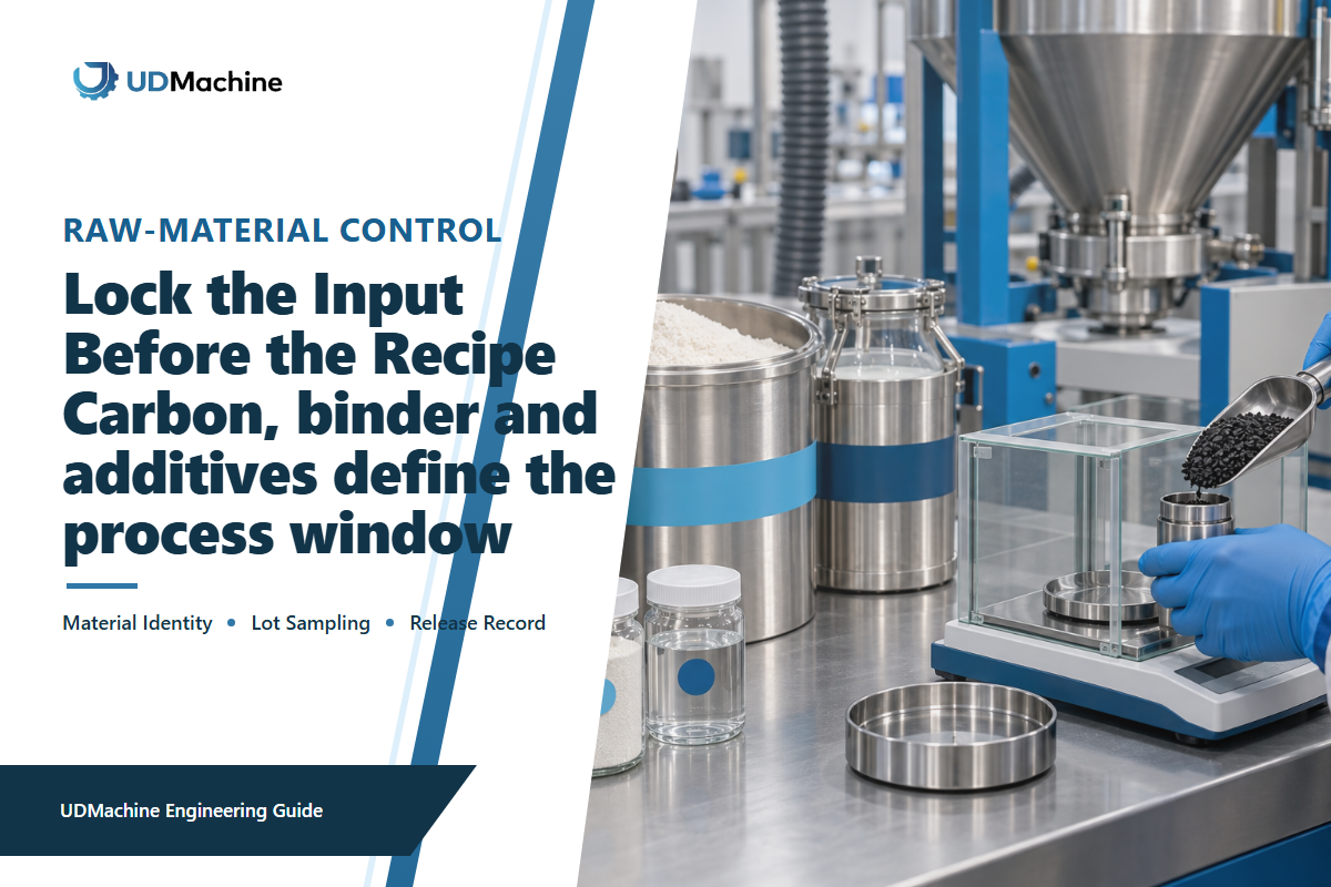
Activated carbon isn’t one single powder. Feedstock, activation route, pore structure, particle distribution, apparent density, moisture, and surface chemistry all matter. These properties can change how a blend feeds and forms. The US EPA overview of drinking-water treatment technologies mentions that activated carbon’s adsorptive capacity is dependent on the raw material, the method of carbon production, the characteristics of the carbon, and the characteristics of the influent. The same variability is a reason to individually craft each manufacturing formulation rather than blindly copying a public recipe.
The choice of binder and distribution of particles affects carbon. Binder needs to be sufficient enough for structure building, but the manufacturing team needs to ensure the structure doesn’t compromise the flow and adsorption behavior. Powder flow and thermal behavior can be influenced by moisture content. Segregation creates a production risk because failed uniform feeding makes variations seem random along a continuous line. A published patent provides one solution with a combination of the ranges of mesh size, binder, heat, feed, and the screw, but this is just a design path, not a universal approach or opinion on the freedom to operate.
Before a controlled trial, freeze the supplier, material code, lot, carbon source, particle specification, binder identity, measured moisture, charge weights, and preconditioning. If any of these change, consider the subsequent output as a new trial condition. Otherwise, a setting change can be credited for an improvement that actually came from a different material lot.
Find the Real Bottleneck in Good-Cartridge Output
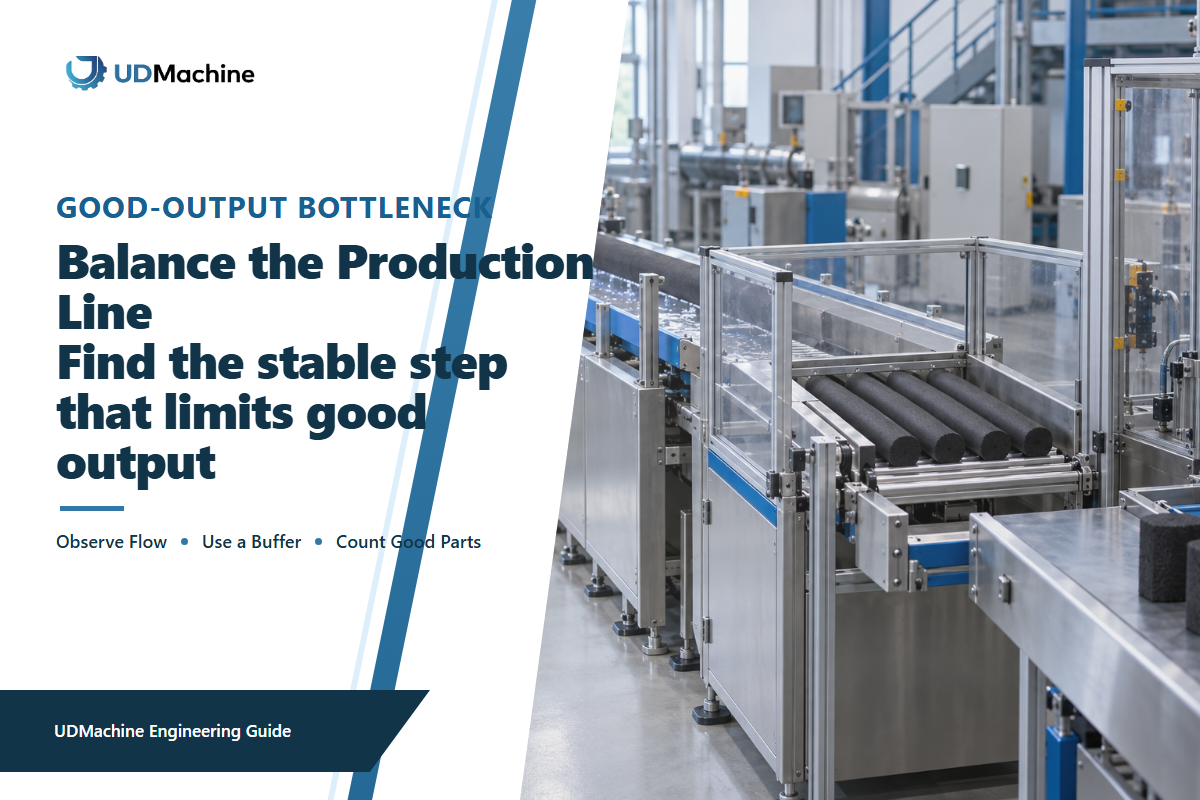
Nominal capacity answers how fast a piece of equipment can cycle under stated conditions. It doesn’t describe how many accepted blocks can be loaded and packed at the end of a shift in a given factory. For that description, count the losses between the various processing stations. The same published extrusion evidence shows why feed, thermal, and screw variables can constrain output before cooling and cutting add downstream losses.
Good-block output
Accepted pieces = start pieces − startup scrap − process rejects − handling damage − test rejects
Perform a short time study on the entire line. Mark the time a controlled batch enters the mixer, each interruption of the feeders, extrusion alarm, cooling stop, blade change, inspection result, and the final count that’s accepted. Categorize losses at the respective stations rather than grouping all rejects under “extrusion.” A cracked block can originate from formulation, thermal history, cooling support, cutting shock, or even from later handling.
This whole-line view also alters capital decisions. If cooling residence or cutting reliability limits accepted output, a faster extruder alone may not improve the business result. If the material refill interrupts the continuity of the feed stream, a buffer or a change in handling would be more important than a marginal increase in motor power. The right decision is based on timed evidence at all of the handoffs.
Build a CTO Process Control Sheet
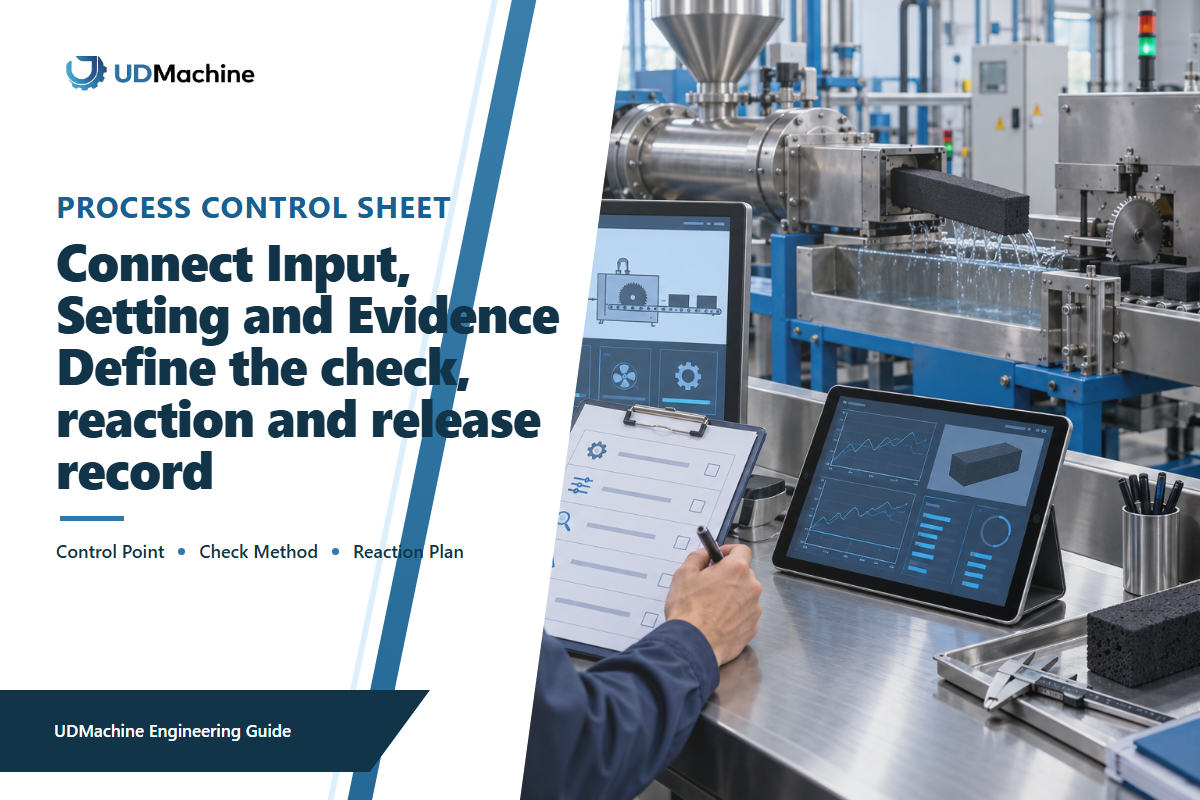
In practice, a useful process sheet connects each setting to a material identity, a measurement, and a decision. The EPA treatment-technology overview supports the material-identity field because activated-carbon behavior varies with raw material and production method. It should be filled out during the process and not be completed after the outcome has been determined. Change one variable at a time if possible. Simultaneous changes may create a good sample and outcome, but it won’t show which of the changes actually affected the outcome.
| Field | Illustrative entry | Why it matters |
|---|---|---|
| Trial and sample ID | TR-07 / S07-001 to S07-020 | Keeps settings, blocks, and results traceable |
| Frozen inputs | Material codes, lots, measured moisture | Separates material change from machine change |
| Changed variable | One named setting; previous and new value | Preserves causal diagnosis |
| Held variables | All other approved recipe fields | Prevents an uncontrolled multi-variable trial |
| Measurements | Dimensions, mass, density proxy, visible defects, pressure-drop method | Connects the change to a defined output |
| Deviation and action | Stop, segregate, correct, restart from named check | Makes abnormal output containable |
| Decision | Accept, reject, or repeat with reason | Stops a visually pleasing sample becoming an unqualified recipe |
| Restart condition | Named check completed; affected material contained | Prevents an unexplained stop from becoming the next trial baseline |
The examples given are just that: examples. Your limits must be derived from approved drawings, product requirements, risk assessment, and validated methods. Where the process can’t hold a proposed limit, record that deficiency before FAT rather than stretching the limit after the trial.
What Proves a Good Carbon Block and a Good Cartridge?

Begin with physical evidence regarding the line’s ability to produce: length, outside and inside diameters, mass, surface condition, squareness, and any agreed upon density or integrity proxy. Indicate sampling frequency and instrument resolution. A number without its flow, conditioning, geometry, and method isn’t a comparison.
Please retain one identified filter sample from the machine trial and one identified filter sample from the finished product test. An identifiable physical chain makes subsequent deviations much easier to identify.
Pressure drop indicates hydraulic resistance; by itself, it does not prove treatment performance. A denser, less permeable structure may increase pressure drop at a given flow. However, pressure loss may also be attributed to geometry, fines, test setup, fouling, or other restrictions. As noted in the University of Nebraska-Lincoln activated-carbon guide, adsorption breakthrough can occur without a corresponding pressure change. Don’t interpret pressure drop as an indicator of adsorption capacity.
For the finished cartridge claim, please retain a complete acceptance packet:
The 9-Point Good-Block Evidence Matrix
The values provided illustrate how conditions and results are interrelated. They’re representative values and not a UDTECH specification or recommended acceptance limits. Replace every value with the drawing, method, and limits agreed for your own product.
| Evidence type | Illustrative record | Decision use |
|---|---|---|
| Sample identity | 10 pieces, S07-001 through S07-010 | Links every result to one controlled trial |
| Outside diameter | 62.0 mm, 62.1 mm, 61.9 mm | Compares three positions with the approved drawing |
| Inside diameter | 28.0 mm, 28.1 mm, 28.0 mm | Checks the formed flow path |
| Cut length | 250.0 mm, 249.8 mm, 250.1 mm | Tests cut control and repeatability |
| Mass | 180 g, 182 g, 179 g | Flags feed or density variation for investigation |
| Conditioning | 23 °C for 24 hr | Makes samples comparable before a hydraulic test |
| Test flow | 4.0 L/min, 4.0 L/min, 4.0 L/min | Fixes the basis of pressure-drop comparison |
| Pressure drop | 18 kPa, 19 kPa, 18 kPa | Records a hydraulic result without turning it into a treatment claim |
| Deviation response | 0 open deviations; 1 retained sample | Closes or escalates the trial with a traceable owner |
- sample and material lot identity;
- drawing and specification revision;
- test method and any applicable standard edition;
- instrument identification, calibration, flow, temperature, conditioning, and challenge conditions;
- acceptance limit, actual result, deviation, and retest rule;
- reviewer and buyer-supplier sign-off.
NSF/ANSI 42-2025 is a current revision for aesthetic-effect systems. The public ANSI summary describes changes to areas such as exposure, extraction, reporting, detection limits, and commercial modular claims. Refer to the applicable full standard and certification body for the actual procedure. A production line cannot be described as “NSF certified” merely because it makes blocks intended for products that may later be tested.
Troubleshoot Defects with Evidence, Not Guesswork
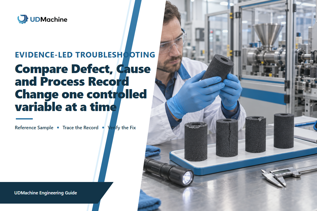
When symptoms appear due to output changes, trace back to the cause instead of blaming everything together. It is counterproductive to rapidly adjust the binder ratio, heat, feed rate, and line speed. That may make symptoms disappear for one batch while the cause of the problem remains unknown. The University of Nebraska activated-carbon guide adds a useful restraint: pressure change and adsorption exhaustion do not reliably move together, so a pressure-drop symptom needs method and geometry checks before a treatment conclusion.
| Symptom | Check first | Evidence to compare | Avoid |
|---|---|---|---|
| Cracks or chipping | Location and time of first appearance | Material lot, thermal history, cooling support, blade state, handling | Calling every crack a binder problem |
| Pressure-drop spread | Test repeatability and geometry | Flow, temperature, conditioning, mass, dimensions, sample order | Comparing values from different methods |
| Visible fines | Cut face and handling route | Blade condition, dust capture, packaging abrasion, rinse test | Assuming all fines formed in extrusion |
| Length variation | Cut trigger and profile motion | Encoder or sensor record, line speed, slip, blade timing | Correcting extrusion heat first |
| Color or surface change | Material identity and thermal exposure | Lot, residence event, zone record, startup or shutdown state | Releasing on appearance alone |
Contain affected material, label the time window, compare accepted and rejected samples, and restart from a named verification point. This will make the succeeding runs informative even if the first attempt to correct the issue wasn’t successful.
Plan FAT and SAT Around a Frozen Product Definition
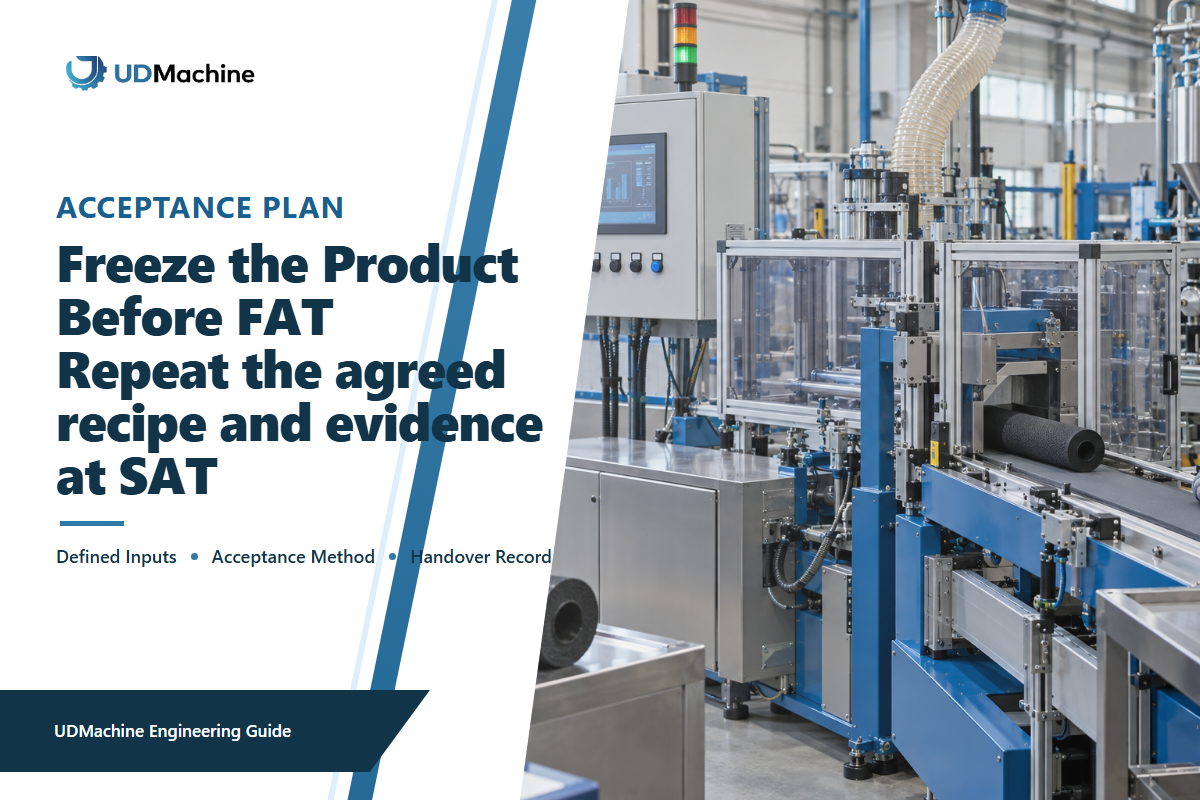
Factory acceptance testing and site acceptance testing are tools used in the contract instead of universal carbon-block standard acceptance testing. They have value only when the acceptance scope is mutually agreed upon before the test and tied to a frozen product definition.
For FAT, freeze the material codes and lots, drawing revision, target geometry, sample size, operating window, test methods, acceptance limits, reject definitions, restart rules, and documents to be delivered. Agree on what simulated utilities and environmental conditions will be. A pre-shipment trial can show that the line runs an agreed material under factory conditions; it can’t qualify every future carbon and binder combination.
SAT checks what changes after installation: site power and utilities, material handling, dust extraction interfaces, layout, operator practice, instruments, local environment, and downstream handling. Use the same sample identity and measurement logic for the factory and site results. If the customer changes the formula, drawing or process, document the change. Don’t consider this a direct repeat.
Minimum acceptance packet
Frozen input list + approved drawing + trial record + station alarms and deviations + identified samples + measurement results + reject count + retained samples + open-item list + signed decision.
According to UDTECH, the company provides design, manufacturing, and commissioning services for filter-cartridge production lines and test-runs equipment before shipment. The company profile clarifies that manufacturing role. Your purchase specification should still indicate the FAT and SAT evidence that you require for your product.
Safety Checks Belong in the Process Plan
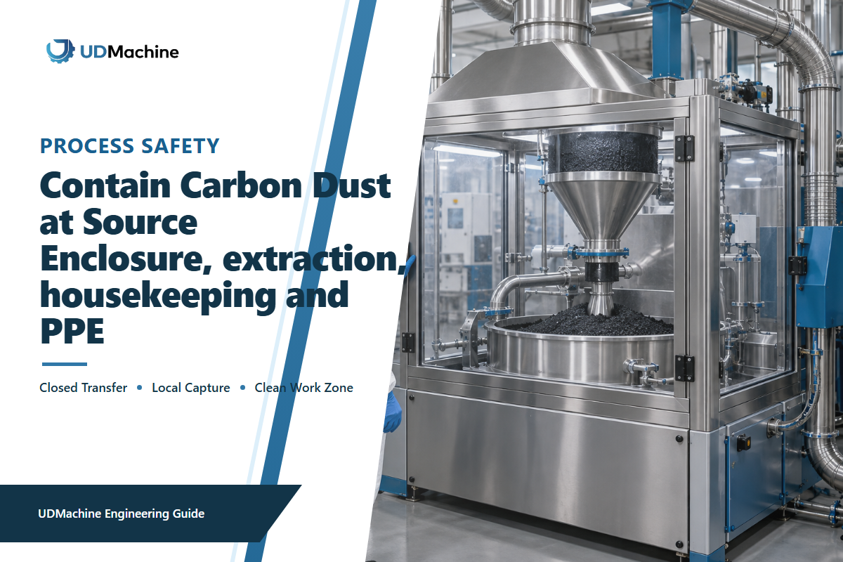
At a production site, fine carbonaceous material can create a combustible-dust risk because a failed capture point or new ignition source can change the hazard. The OSHA combustible-dust overview mentions carbonaceous materials as an example, but doesn’t establish a generic hazard classification based on the formulation of carbon. Material testing, dust characteristics, quantity, containment, ignition sources, ventilation, cleaning, and site-specific rules are among the factors to consider.
Review the generation of dust during charging, transfer, feeding, cutting, collection, and removal. Also review access to moving parts, hot surfaces, cutters, stored energy, guards, interlocks, isolation, extraction, and personal protective equipment, with observed dust, capture condition, housekeeping, and ignition-source controls documented at charging and cutting stations. This guide isn’t meant to certify a facility or provide a generic control package.
How to Evaluate a Line Without Creating Keyword Cannibalization

When speaking to the supplier, ask if they can run the specified materials, if the six transfers are stable, if meaningful measurements can be made, if deviations can be recovered, and if traceable samples can be provided. Ask for evidence that relates agreed trial inputs to the agreed output. Product-specific treatment and certification questions should stay separate; the 2025 ANSI scope summary describes procedure changes for aesthetic-effect systems without turning a production line into a certified product. In isolation, a list of motors, automation, or upper limits can’t answer these questions.
Use the solution page to compare configuration, capacity, size, utilities, price, MOQ, lead time, quotations, and RFQ requirements. That commercial page is for buyers comparing equipment options. This guide is for engineers and managers working on process control and acceptance. Evidence should be presented, and the intended test method should be explained. The shared keyword is intentional, but the search task and conversion route are different.
Bring a real product definition to the machine discussion
Prepare your cartridge drawing and material list. Provide your target evidence, and your planned method of acceptance. With that, UDTECH can discuss relevant trial boundaries and the configuration of a line.
Frequently Asked Questions
What is a CTO activated carbon filter cartridge machine?
A CTO activated carbon filter cartridge machine mixes and feeds carbon and binder, forms a continuous profile, cools it, cuts it to length, and manages dust. Its direct output is a cut carbon block. Wrapping, end caps, gaskets, marking, packing, and final qualification may remain downstream. Buyers should define those boundaries because a visually acceptable block alone does not prove chlorine reduction, pressure drop, service life, material safety, or certification. Define the machine boundary before comparing capacity, tooling, or automation.
Can one machine recipe work with every activated carbon?
There’s no universal recipe. Variables such as the source of carbon, the distribution of carbon, the particle size, the moisture content, the compatibility of the binder, the shape, and the objectives of the process can affect the process window. Validate a formulation and the controlled material, and document the changes in a controlled manner, rather than relying on published values.
Does a low pressure drop prove better chlorine reduction?
No. Pressure drop is a hydraulic effect caused by flow, geometry, conditioning, density, fines, test setup, and permeability. A chlorine-reduction claim is product-specific and requires a defined test. Reporting the results of both with their respective methods would be proper rather than using one result to replace the other.
What should be checked during FAT?
Freeze the material lot, drawing, product geometry, operating window, sample size, measurement methods, limits, reject definitions, restart rules, and document package before FAT. Retain identified samples and record deviations. Prove only the agreed factory scope, not every future product variation.
Why is accepted output more useful than extrusion speed?
Extrusion speed describes one station. Accepted output also counts losses from startup, feeding, cooling, cutting, handling, inspection, and test rejects. Counting accepted blocks over a defined production period identifies the real constraint and gives a more accurate cost-per-good-piece comparison basis.
References & Sources
- US EPA: Overview of Drinking Water Treatment Technologies
- University of Nebraska-Lincoln: Drinking Water Treatment with activated carbon
- NSF: NSF/ANSI 42, 53 and 401 Filtration Systems Standards
- ANSI: NSF/ANSI 42-2025 Update Summary
- OSHA: Combustible Dust
- WaterWorld: Carbon Block Manufacturing
- US20090274893A1: Extruded Carbon Block Process Disclosure
This article cites public first-party, government, university, standards-owner, industry, and patent sources in English. Illustrative worksheets and acceptance packets are aids for planning, and should not be construed as recipes for compliance or certification.
UDTECH / ENGINEERING GUIDE
About UDMachine
UDTECH publishes practical production-line planning guides for filter cartridge making, assembly, finishing, and complete-line projects.
Use these guides to define cartridge type, process route, target output, available utilities, acceptance evidence, delivery scope, and installation constraints before selecting equipment.
Start with the cartridge
Media, diameter, length, end-cap format, and rated output define the real machine route.
Clarify the line scope
Utilities, layout, automation level, inspection points, and acceptance tests vary by project.
PRODUCT / CAPACITY / ACCEPTANCE
Prepare Your Line Brief
Product types
PP Melt Blown · String Wound · CTO Carbon · UDF Tube
Start with
Cartridge type · Target output · Country
Planning inputs
Utilities · Layout · Process · Acceptance standard
Response route
Submit the website inquiry form
Submit Project Brief