Get in touch with Suzhou UDTECH Technology Co., Ltd. Company

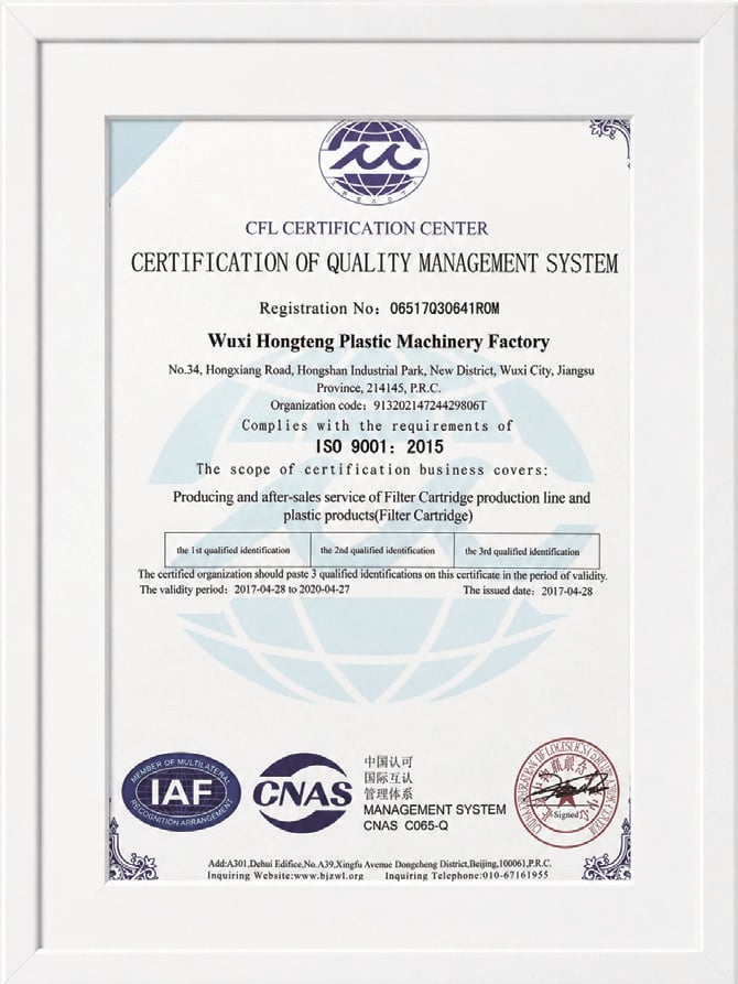
ISO Certified Process
Filter Cartridge Assembly Process
Filter Cartridge Assembly Process and Equipment Solutions
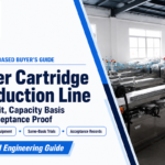
Start the filter cartridge assembly process with the cartridge construction, not a generic machine catalogue. UDTECH then maps forming, cutting, wrapping, welding, capping, inspection, and material handling into a line scope that engineering and purchasing teams can review before releasing an order.
- Engineer-reviewed quote within 24 hours on business days
- Production scheduled 30-60 days after technical approval and deposit
- MOQ: 1 machine or production-line set
Send Your Cartridge Specification
Start with a cartridge drawing or sample, material list, target output, SKU mix, power supply, and required acceptance tests.
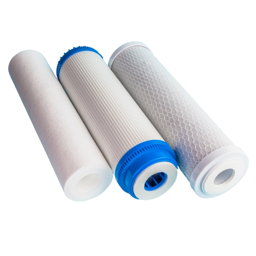
Filter Cartridge Assembly Summary at a Glance
24 hours
Quote response on business days
30-60 days
Production after technical approval and deposit
1 machine or line set
Minimum order, subject to configuration
ID 9-100 mm
Published CTO configurable range
OD 29-150 mm
Published CTO configurable range
50-60 seconds
Published cycle for one 10-inch CTO cartridge
Decision checkpoint
The range and cycle values above belong to the brochure’s CTO equipment scope. We confirm the required extruder configuration, matching parts, downstream stations, and acceptance method against your actual product before the offer is fixed.
Filter Cartridge Assembly Capabilities Across Production Stages
The right assembly machine and surrounding production line depend on the cartridge family, material route, joint design, output target, and changeover pattern.
Filter Cartridge Assembly Process Flow Diagram
01
Mix
Carbon and binder recipe
02
Feed
Stable material delivery
03
Extrude
Configured ID and OD
04
Cool
Support the formed rod
05
Cut
Length control
06
Collect Dust
Project-specific screening
The brochure’s CTO route combines automatic mixing, feeding, extrusion, cooling, cutting and dust collection. Independent process literature also separates carbon-block extrusion from downstream finishing.[8] Wrapping, joining, end-cap work, inspection, and packing are scoped separately so an omitted interface does not appear later as an unplanned purchase.
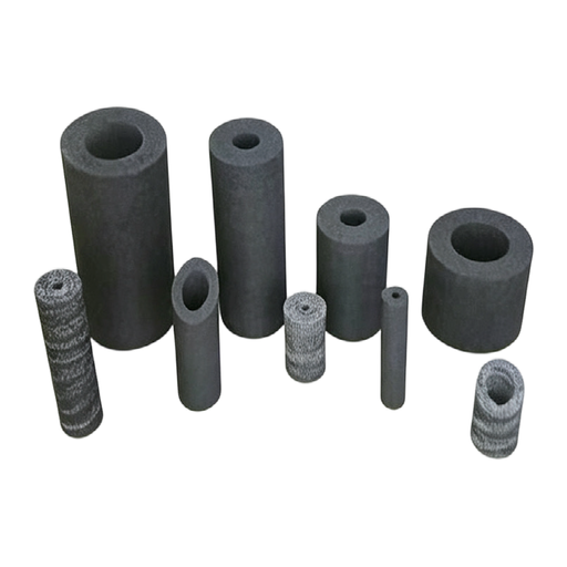
CTO Carbon Block Forming
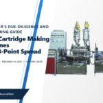
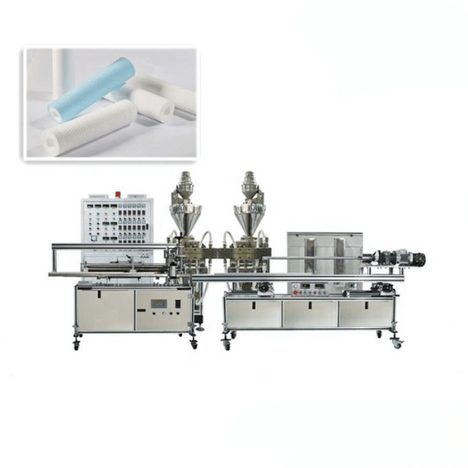
We configure the carbon-block filter making machine around activated-carbon granules, PE powder, the required inside diameter, outside diameter, cartridge length, and output. Material feed behavior and dust-control inputs belong in the technical review before tooling is selected.
External Wrapping and Welding
Our brochure-listed downstream machine provides external carbon-rod wrapping and welding. Its automatic sequence includes automatic carbon-rod ejection, non-woven wrapping and automatic discharge.
PP Melt-Blown Production
UDTECH supplies PP melt-blown filter production lines for polypropylene depth-filter manufacture. This is a melt-blown filter cartridge machine route, not a carbon-block extrusion or string-winding conversion.
String-Wound Cartridge Production
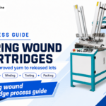
UDTECH supplies winding equipment for PP yarn and other approved string-wound filter inputs. Wound filters require their own core, yarn tension, winding pattern, diameter, and length definition.
Station Scope to Freeze Before Quotation
- Raw-material preparation, feeding, forming, and scrap or dust collection
- Center tube or core handling, filter media conversion, pleat or winding route where relevant
- Cutting, external wrap, end cap, adhesive or heat-welding method, and seal construction
- Buffering between stations, operator tasks, line controls, safety devices, and change parts
- Inspection samples, trial material, factory acceptance records, packing, installation, and training scope
Machine Modules and Controls Resolved During Design
Material Preparation
Scoop feeders, a transfer pipe, a storage cylinder, dosing components, and dust collection are selected from the powder or pellet behavior. A stable feed matters because particle segregation or changing viscosity can alter the formed carbon block.
Media Conversion
Filter paper, wood pulp media, textile fiber yarn, membrane, polyester, filter cloth, and mesh do not share one conversion route. Slit width, perforate pattern, yarn winding, pleating machine settings, and the number of pleats are product inputs.
Handling and Motion
A gripper, servo axis, pneumatic cylinder, internal support, or outer cage handling module is added only when the component and takt plan require it. We automate the transfer that limits production consistency instead of adding motion without a measurable purpose.
Joining Hardware
Hot melt, hot melt adhesive, metered glue, ultrasonic welding, ultrasonic weld machines, a thermal welder, or a metal clip can suit different assembly methods. The bond, seam, O-ring, cap resin, and leakage criterion determine the route.
Control Architecture
We equip the assembly line with the controls needed for recipes, position checks, alarms, rejects, and secured operating access. Fully automated motion, fully automatic assembly, and automatic filter assembly are quoted only where the process and SKU plan support them.
Final Handling
Final assembly, label handling, inspection, and packaging operations are balanced with the production station. Shrink packaging equipment is a separate option, not an assumed part of every filter cartridge machine.
Naming alignment
Specifications use overlapping names such as automatic filter, automatic cartridge assembly machinery, filter assembly machine, cartridge assembly machine, cartridge production line, and filter cartridge machines. UDTECH normalizes those labels into a station list so the buyer, supplier, and machine manufacturer compare the same scope.
Cartridge Types, Materials, and Process Fit
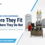
Choose a cartridge making machine only after the media structure and joining route are fixed. Matching outside dimensions do not make CTO, PP melt-blown, string-wound, and pleated filter cartridges compatible with the same process.
| Cartridge family | Primary forming route | Assembly focus | Inputs that control fit |
|---|---|---|---|
| CTO activated carbon block | Blend, feed, extrude, cool, and cut activated-carbon granules and PE powder[8] | Nonwoven wrap, weld, end-cap route, and final inspection | Carbon grade, binder ratio, particle behavior, ID, OD, length, output, and dust review |
| PP melt-blown cartridge | Melt-blown polypropylene fiber deposition | Length finishing and any specified core, adapter, or end treatment | Polymer, filtration gradient, diameter, length, weight, and thermal process window |
| String wound filter | Controlled yarn winding around a center core | Pattern consistency, end finishing, and dimensional inspection | PP yarn or approved fiber, core material, winding density, diameter, and nominal retention target |
| Pleated filter cartridge | Media pleat formation, seaming, and pack sizing | Core/cage insertion, end cap or potting, seal, and integrity inspection | Filter media, pleat count and height, support layers, adhesive or weld route, gasket, and filter housing interface |
| Input group | Terms to define in the RFQ | Why the line design changes |
|---|---|---|
| Construction | Types of filter cartridges, categories of cartridge, cylindrical geometry, inner core, center tube, internal component, internal support, outer cage, pleated media, membrane pleated pack, or pleated block | The type of filter controls forming, support, handling, joining, and final assembly. |
| Hydraulic or airflow duty | Flow rate, higher flow rates, high flow, high-flow duty, high flow filter format, pressure drop, differential pressure, high pressure, pressure conditions, and process fluid | These inputs change filtration area, surface area, housing fit, structural support, and test conditions. |
| Separation target | Pore size, pore structure, micron statement, dirt-holding target, suspended solids, contaminants found, filtration efficiency, efficiency claim, and filtration requirements | A precise target connects the filter material and filtration process to a test method instead of a marketing label. |
| System context | Filter housing, filter vessel, number of cartridges, pre-treatment, prefiltration, liquid filtration, water filtration, water purification, drinking water, air filter, or industrial filter service | The filtration system determines interfaces, cleanliness, flow distribution, and release evidence. |
| Special materials | Quality membrane, stainless steel, sintered metal, filter bags, filter bag, polyester, filter cloth, mesh, or another approved filter material | Material form and temperature change the suitable making machine, joining method, and inspection route. |
| Controlled applications | Food and beverage, pharmaceutical, sterile filtration, electronics, automotive, or other various industrial filtration needs | Cleanliness, traceability, sterilization, chemical compatibility, and application-specific qualification must be defined by the product owner. |
Water Treatment and Purification
For a water filter cartridge making machine enquiry, identify whether the final product is a sediment filter, CTO taste-and-odor cartridge, chemical-reduction filter, or another cartridge filter design. The intended claim determines the product test plan; the machine alone does not establish that claim.
Industrial, Beverage, and Air Filters
Industrial filtration, beverage processing, and air filters can use different media, seals, housings, cleanliness controls, and release criteria. We use the intended fluid or air service as an RFQ input while the product owner defines the applicable validation and regulatory route.
Process Language in a Mixed Supplier Market
A melt blown filter making machine produces a spun filter cartridge through a melt-blown polymer route. A PP string wound filter uses a string wound filter cartridge machine or wound filter making machine, while pleated cartridges and each pleated filter cartridge require a pleated filter process.
A filter cartridge making machine, cartridge making machine, or making machine label is not enough to establish compatibility.
A production process becomes reviewable when cartridge manufacturing inputs, filter manufacturing stages, assembly process steps, and machine features are named.
We customize the US-English specification and can customise a buyer’s UK-English schedule; the same customization decisions remain tied to the approved drawing.
Pleated-Line Boundary
Within the filter manufacturing industry, an automated pleated filter cell can combine continuous media feed with multi-stage cutting, pleating, pack handling, and assembly. High filtration efficiency remains a finished-product claim that requires the defined media, geometry, seal, housing, flow, and test method.
Material Handoff
Send the material specification and safety data sheet for every powder, polymer, adhesive, nonwoven, gasket, and end-cap resin. This lets the process review cover compatibility, temperature, handling, ventilation, dust, and contamination controls before the filter machine layout is approved.
Wrapping, Joining, and End-Cap Methods
The joining route follows the media, end-cap material, seal design, temperature window, chemical exposure, and test requirement. That route is frozen before fixtures, heating, adhesive dispensing, or handling automation enter the quotation.
Small and Manual End-Cap Welding Routes
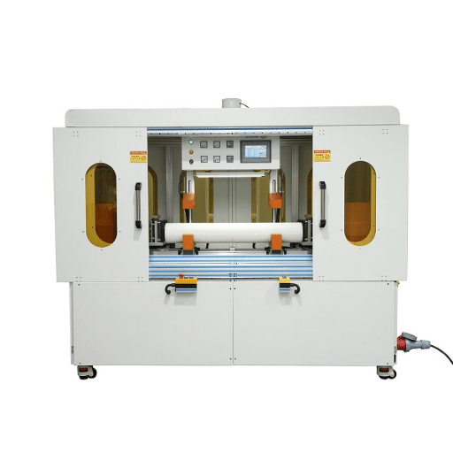
Small Filter Cartridge End Cap Welding Machine
A compact station still needs the cap resin, media pack, joint geometry, heating method, fixture, cooling, and integrity criterion. “Small” describes the equipment footprint or product envelope, not the strength of the finished joint.
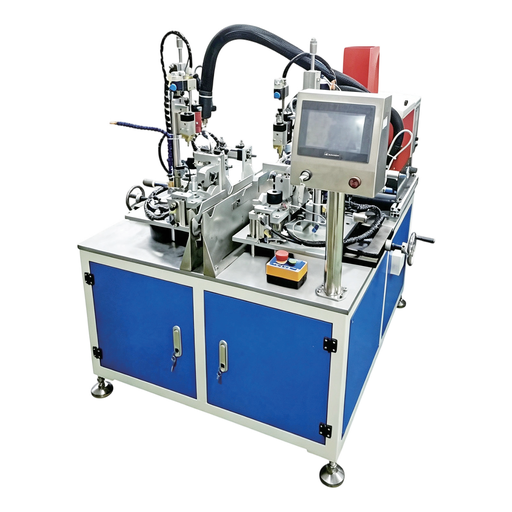
Manual Filter Cartridge End Cap Welding Machine
A manual loading route can fit frequent model changes or a lower launch volume when operator work is controlled. The trade-off is that loading position, heat cycle, dwell, cooling, and first-piece inspection must remain repeatable.
Operation
Process choice
Critical input
Evidence to request
External carbon-rod wrap
Non-woven wrapping with automatic ejection and discharge on the referenced machine
Rod diameter, wrap material, overlap, tension, and length
Wrapped sample, seam position, coverage, and handling observation
Wrap seam
Heat-welding method on the referenced downstream machine
Nonwoven composition, heat window, weld width, and line speed
Visual seam criteria and pull or peel method agreed for the product
End-cap bond
Adhesive, thermal fusion, overmolding, or mechanical sealing according to construction
Media embedding, cap resin, adhesive chemistry, cure time, and gasket design
Sectioned first article, continuity check, cure record, or integrity test as specified
Core and cage
Insert, weld, bond, or mechanically retain according to the cartridge design
Collapse requirement, flow path, concentricity, and housing fit
Drawing inspection and functional sample fit
Final length and interface
Cut, trim, adapter, gasket, and label operations
Overall length, end geometry, seal location, and orientation
Dimension report and approved master sample
Do not approve a joining station from a clean-looking outside seam alone. Put the joint section, media embedding, seal continuity, and agreed integrity result into the acceptance record.
Udtech Engineering TeamWhy the route matters
A thermal cycle that suits one cap polymer can distort another, while an adhesive route adds dispensing and cure-time constraints. Patent literature shows several workable end-cap architectures;[7] your drawing and product validation decide which one belongs in the line.
Release Conditions for the Joint
- Record the operating conditions, high-temperature exposure, chemical contact, and any requirement to sterilize the filter element.
- Set dimensional precision, visible-defect limits, bond coverage, seal continuity, and the relevant pressure conditions.
- For a membrane or quality membrane product, define the applicable integrity and retention tests after the joint is made.
- High quality is an approved result against those criteria; a high-quality appearance alone does not release the cartridge.
CTO Line Configuration and Published Operating Range
The table sets out the published envelope for the referenced CTO equipment, with calculated inch or millimetre equivalents for comparison. We still confirm the order configuration against a drawing and sample because the extruder runs one ID/OD combination unless matching parts are replaced.
| Specification | Published value | Configuration note |
|---|---|---|
| Standard inside diameter | ID 38 mm (1.50 in) | Custom configuration available within the stated range |
| Standard outside diameter | OD 63 mm (2.48 in) | Custom configuration available within the stated range |
| Configurable inside diameter | ID 9-100 mm (0.35-3.94 in) | Confirm tooling and matching parts for the required ID |
| Configurable outside diameter | OD 29-150 mm (1.14-5.91 in) | Confirm tooling and matching parts for the required OD |
| Listed cartridge lengths | 5, 10, 20 and 30 inch (127, 254, 508 and 762 mm) | Custom lengths are available after engineering review |
| Published output | One 10-inch cartridge every 50-60 seconds | Referenced CTO configuration only; complete-line output also depends on downstream balance |
| Extruder size setup | 1 ID/OD production configuration | Replace matching parts when the required ID/OD combination changes |
| Downstream machine supply | AC 220 V / 50 Hz | Electrical supply for the brochure-listed gluing/capping machine |
| Downstream rated power | 2,000 W | Rated power for the brochure-listed gluing/capping machine |
| Downstream controls | PLC and HMI control | Confirm recipes, alarms, interfaces, and language in the technical agreement |
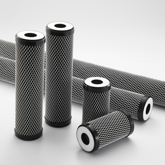
The gluing and capping machine specification is AC 220 V / 50 Hz, 2,000 W rated power, PLC and HMI control. Utilities for the upstream production line, ventilation, compressed air, cooling, extraction, and any local electrical conversion are confirmed separately.
Evidence boundary
The dimensional and cycle values above come from the supplied UDTECH brochure. The independent carbon-block source supports the extrusion and downstream-finishing route, not those supplier-specific dimensions or output values.
ASSEMBLY PROCESS
Quality Control and Line Acceptance Planning
The acceptance plan starts with the approved cartridge, process settings, station functions, safety review, output definition, and evidence record. This keeps a machine dry run from being mistaken for approval of the finished filter cartridge.
❮
❯
Factory Acceptance Evidence
Freeze the test object.
Approve the drawing, materials, sample quantity, machine scope, utilities, and change parts used for the run.
Verify station functions.
Record start, stop, recipe, alarm, guarding, interlock, handling, and reject responses that belong to the supplied equipment.
Run agreed samples.
Observe forming, wrapping, weld or bond, cutting, dimensional consistency, surface condition, and visible defects against written criteria.
Measure line balance.
Record each station's cycle, buffer behavior, operator intervention, stoppage, and net accepted output rather than extrapolating from the fastest station.
Close deviations.
Assign the correction, evidence owner, retest condition, and sign-off before shipment or site acceptance.
| Evidence Lane | What It Establishes | What It Does Not Establish | Reference Framework |
|---|---|---|---|
| Automation-system FAT/SAT | The supplied controls and automation functions meet the agreed specification at the factory or site. | It does not certify filtration performance or approve every future SKU. | IEC 62381:2024 concepts; project protocol controls the actual scope. |
| Machinery risk review | Hazards and risk-reduction measures are considered across the machine life cycle. | It is not a product-efficiency test or an automatic machine certification. | ISO 12100:2010 methodology and applicable local requirements. |
| Finished-cartridge validation | The product meets defined integrity, hydraulic, material-safety, structural, or claim-specific performance criteria. | A bubble point alone does not establish filtration rating, efficiency, or retention capacity. | An applicable product route, such as ISO 2942, ISO 16889, or a claim-specific NSF/ANSI drinking-water standard selected by the product owner. |
Product standard boundary
ISO 2942:2018 addresses fabrication integrity and first bubble point for hydraulic filter elements. ISO 16889:2022 defines a hydraulic multipass test, while drinking-water certifications are claim-specific; choose standards from the actual filter, housing, fluid, contaminant claim, and market—not from the assembly machine name.
×
![Enlarged view]()
Ordering Workflow: From Cartridge Specification to Line Acceptance
The engineering handoff converts product inputs into a controlled equipment scope and carries the same approved requirements through factory acceptance, site handoff, and after-sales support.
Submit the Product Pack.
Send drawings or samples, cartridge family, materials, ID, OD, length, interfaces, application, and expected variants.
Map the Process.
We identify the forming, cutting, wrapping, joining, capping, inspection, material-handling, and packing stages required for the stated product.
Freeze Utilities and Boundaries.
Both sides mark existing equipment, buyer-provided services, extraction, cooling, air, power, floor space, and data interfaces.
Review Line Balance.
We compare target sellable output with station cycles, buffers, curing or cooling time, changeover, inspection, and operator work.
Issue the Written Offer.
The quotation identifies supplied machines, options, matching parts, controls, tests, commercial terms, and project milestones.
Approve Technical Details.
Drawings, recipes, sample materials, safety inputs, and acceptance criteria are signed off before production is scheduled.
Witness and Close FAT.
The agreed cartridge and protocol are used to record functions, samples, output, deviations, and retest evidence.
Complete the Handoff.
Installation, training, spares, site acceptance, and ongoing technical after-sales responsibilities follow the agreed order scope.
RFQ Inputs That Prevent Rework
| Input | Minimum Useful Detail | Decision It Unlocks |
|---|---|---|
| Product Definition | Drawing or sample, ID, OD, length, end interface, filter housing fit | Tooling, fixture, handling, and change-part concept |
| Material Package | Media, carbon, binder, yarn, core, nonwoven, cap, adhesive, gasket, SDS | Process temperature, compatibility, feed, joining, and safety review |
| Production Target | Accepted pieces per shift, shift pattern, SKU mix, changeover frequency | Automation level, station count, buffers, staffing, and test duration |
| Acceptance Package | Dimensions, visual limits, integrity test, sampling, records, witness points | FAT equipment, sample quantity, protocol, and release criteria |
Selection Result
The review ends with a precise, secure technical schedule: suitable machine modules, process conditions, target filtration performance, test responsibilities, and the open inputs that must be closed before manufacture. This is how we minimize late changes and protect both production consistency and final-product reliability.
UDTECH Equipment and Manufacturing Scope Summary
Suzhou UDTECH Technology Co., Ltd. integrates independent R&D, equipment production, domestic sales, global export, and technical after-sales service for filter manufacturing machinery.
Manufacturing Base
UDTECH operates a 6,000-square-meter standardized workshop for filter-equipment production, supported by manufacturing, laboratory, and testing equipment.
Equipment Portfolio
We specialize in PP melt-blown filter production lines, CTO activated-carbon filter production lines, wire-wound filter machines, and related cartridge assembly equipment.
Export Experience
UDTECH has equipment exported to more than 55 countries, supporting projects across Europe, the Americas, the Middle East, and Asia.
Scope You Can Review in the Offer
Product-to-process assessment based on the supplied cartridge specification
Machine list, automation boundary, matching parts, auxiliaries, and controls
Factory test inputs, sample materials, acceptance criteria, and evidence ownership
Installation, training, spare parts, site handoff, and technical support scope
Qualification Package
Ask for the company documents, machine drawings, electrical list, component schedule, FAT protocol, and service terms required by your vendor-approval process. The written order package, not a generic website badge, should carry the project-specific evidence.
Process Boundaries and Better-Fit Equipment Routes
There is no universally best filter cartridge machine; the fit depends on the product and production pattern. More automation is not always better, a faster station does not necessarily make a faster line, and a wider size range does not mean changeover-free production.
| Situation | Why the proposed route works against you | Better-fit direction |
|---|---|---|
| Many low-volume SKUs change every shift | A tightly integrated fully automatic line can lose time in tooling, recipe, material, and fixture changeover. | Compare a flexible cell or modular machines with the integrated line using actual changeover minutes and staffing. |
| Pleated media is routed to carbon-block extrusion | Pleat forming, pack seaming, core/cage assembly, and potting are not created by an extruder. | Use a pleated-element process map and specify media width, pleat geometry, support layers, joint, and end cap. |
| String wound filters are routed to melt blowing | Yarn winding pattern and tension around a core are different from polypropylene fiber deposition. | Use a winding machine sized for core, yarn, diameter, length, and required winding pattern. |
| The buyer treats maximum station speed as line output | Cooling, cutting, wrapping, curing, inspection, rejection, buffers, and operator tasks can become the bottleneck. | Run a station-by-station balance and define accepted pieces per shift in FAT. |
| The full CTO diameter range must run with no change parts | The brochure states one extruder configuration per ID/OD combination unless matching parts are replaced. | List the launch SKUs, required change parts, setup sequence, recipe retention, and first-piece check. |
| A bubble-point result is used as the entire filtration claim | Fabrication integrity is not the same as efficiency, rating, contaminant capacity, or application certification. | Select the product test program from the filter design, fluid, housing, claim, and destination market. |
Filter Cartridge Assembly Process Tools
01
Filter Cartridge Process Fit Matrix
Choose the cartridge family and production pattern. The matrix returns the core forming route, downstream focus, and the scope questions that belong in your equipment RFQ.
02
Assembly Line RFQ Input Builder
Mark the inputs already available. The builder shows what is still missing from a reviewable filter-cartridge equipment enquiry and creates a list you can copy into your message.
03
Carbon Block Line Boundary and Bottleneck Checker
Enter the observed or planned cycle time for each included stage. The checker identifies the longest station cycle and shows a mathematical ceiling before downtime, rejection, changeover, starvation, or blocking are applied.
Filter Cartridge Assembly Process FAQ
01
01
What stages belong in a filter cartridge assembly process?
The sequence depends on construction. A CTO route can include mixing, feeding, extrusion, cooling, cutting, dust collection, external wrapping, heat welding, end-cap work, inspection, and packing; PP melt-blown, string-wound, and pleated products use different forming stages.
02
02
Can one filter cartridge making machine produce CTO, melt-blown, wound, and pleated filters?
No single forming machine performs all four routes. Shareable downstream operations depend on the drawing, but carbon extrusion, polypropylene melt blowing, yarn winding, and media pleating require different core equipment.
03
03
What controls complete-line output?
Net output follows the slowest constrained stage after cooling, cutting, wrapping, joining, curing, inspection, rejection, changeover, and operator work are included. The brochure lists one 10-inch cartridge every 50-60 seconds for the referenced CTO configuration, not every complete line.
04
04
Does the CTO size range run without a tooling change?
No. The stated envelope is ID 9-100 mm and OD 29-150 mm, while one extruder configuration corresponds to one ID/OD combination unless matching parts are replaced.
05
05
What information is needed for a filter cartridge machine price?
Send the cartridge family, drawing or sample, materials, ID, OD, length, target accepted output, SKU mix, utilities, line boundary, acceptance plan, service scope, and destination. We return the engineer-reviewed quotation within 24 hours on business days.
06
06
What is the minimum order and payment structure?
The MOQ is 1 machine or production-line set, subject to configuration. Orders use a 30% T/T deposit with the 70% balance due after inspection and before shipment, subject to the final contract.
07
07
How long does equipment production take?
Production is scheduled for 30-60 days after technical approval and deposit, confirmed in the quotation. Installation, transit, customs, and site acceptance are separate schedule inputs defined for the order.
08
08
How should FAT differ from finished-filter validation?
FAT verifies the agreed equipment functions, samples, line balance, and records. ISO 12100:2010 informs machinery risk review, while product tests such as ISO 2942:2018, ISO 16889:2022, or a claim-specific drinking-water standard must be selected for the finished cartridge's actual application.
09
09
What should be checked on a wrapped and welded carbon rod?
Check coverage, overlap, seam position, surface damage, dimensions, end preparation, and the agreed seam-strength method. The referenced downstream unit uses automatic carbon-rod ejection, non-woven wrapping, heat-welding, and automatic discharge.
10
10
How should a buyer compare automation levels?
Compare accepted output per shift, operators, buffer behavior, changeover minutes, reject handling, maintenance access, and future SKU count. Fully automatic equipment suits a stable process; a modular arrangement can be easier to adapt when products change often.