Get in touch with Suzhou UDTECH Technology Co., Ltd. Company


Updated September 2026 · By Karry
The UDF tube making machine is used to manufacture plastic supports. These are used in granular activated carbon filter cartridges. The key question in regard to the tube is: does plastic leave the die? But a purchaser is more interested in the included functions, the tolerance limits of an acceptable tube, and the downstream cartridge processes excluded from the tube line.
This guide follows the material from feed preparation through extrusion, cooling, haul-off, cutting, optional perforation, and recorded inspection. Readers not in need of drawing preparation may go directly to the configured UDF tube making machine solution. The remaining items to address are processing-condition qualification with the production resin, drawing revision, utilities, and the customer’s acceptance method.
Quick Scope Check
- Typical input: an approved thermoplastic resin grade and controlled additives.
- Typical tube-line output: a cooled, pulled, cut, and possibly perforated support tube.
- Separate downstream work: carbon filling, separator placement, end-cap joining, and finished-cartridge testing unless expressly included.
- Acceptance basis: the buyer’s drawing, measurement method, sampling rule, and written disposition process.
What a UDF Tube Making Machine Actually Produces
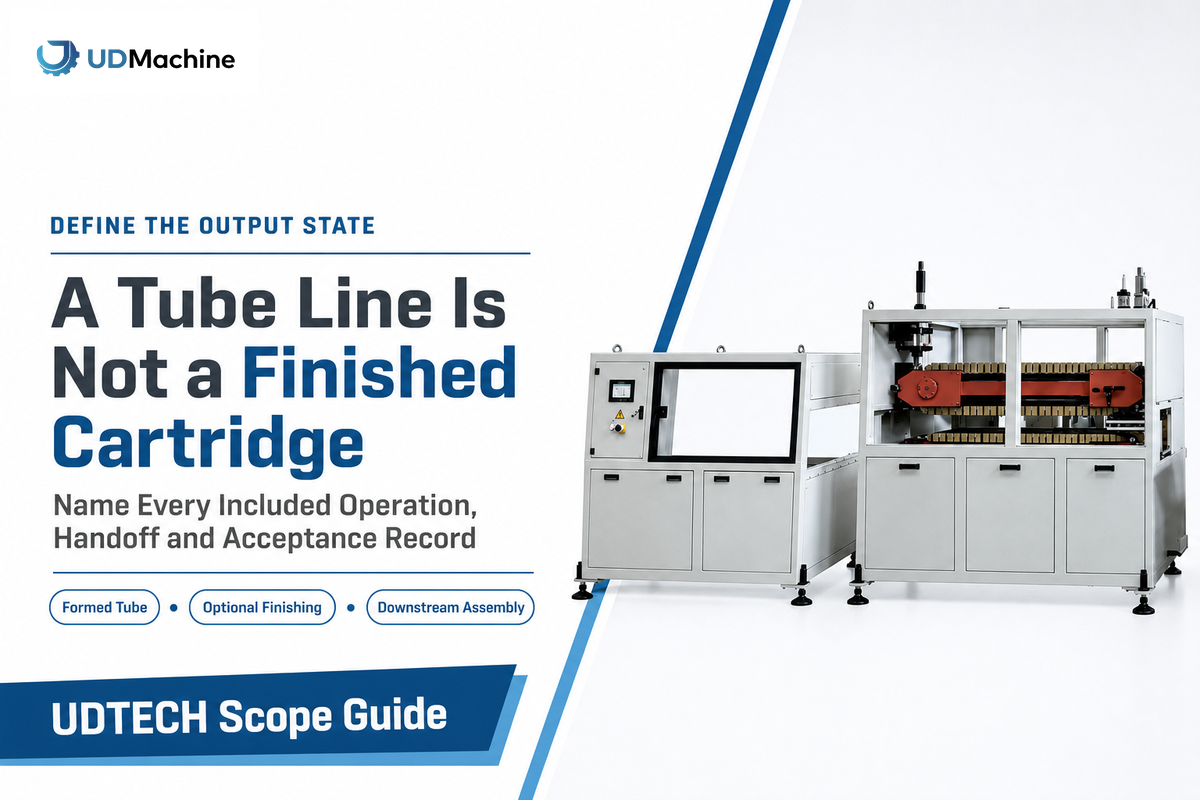
A UDF tube making machine produces a formed plastic support tube, not automatically a finished water-filter cartridge. Its processes include material feeding, plastic extrusion, tube shaping, cooling, haul-off, cutting, and any perforation or cleaning stated in the written scope. Tube finishing may include perforations or cleanings when the written scope includes them. The quoted operations must state whether fusing cartridge end caps and testing the completed product are included.
The distinction is important because “UDF line” isn’t specific. The US Environmental Protection Agency overview of drinking-water treatment technologies states that granular activated carbon is treatment media. The tube line would be the supporting framework that houses or directs treatment media. It wouldn’t be considered a barrier or reduction media and wouldn’t substantiate the finished system’s treatment claims.
Tubular water-filter blocks described in US Patent 8,167,141 B2 define inner and outer dimensions, end surfaces and a flow path characterized by a perforated wall. That teaches the component boundaries, not UDF recipe or tolerance limits. The patent, however, doesn’t disclose a UDF tube-machine recipe or buyer tolerance limits.
| Input | Operation | Output evidence | Next owner |
|---|---|---|---|
| Approved resin | Feed, melt, and form | Material lot and process record | Tube-line owner |
| Hot extrudate | Calibrate and cool | Dimensional readings at stated conditions | Tube-line owner |
| Continuous tube | Pull, cut, and optionally perforate | Length, edge, and pattern inspection | Tube-line owner or separate finisher |
| Prepared tube and media | Fill and place separators | Batch and fill records | Cartridge-assembly owner |
| Assembled cartridge | Join end caps and test | Finished-product inspection and claim evidence | Finished-product owner |
A seller’s statement that a line can run for 24 h is still an operating claim, not proof that the quotation includes carbon filling, assembly, or 24 h of accepted output. As such, the quotation must include a statement on carbon filling, assembly, 24 hours of run time, and the acceptance basis. The purchaser’s document must identify each of the operations, interfaces, acceptances, inspections and transitions in the process, rather than using the term “line.”
The Five-Stage UDF Tube Manufacturing and Extrusion Sequence
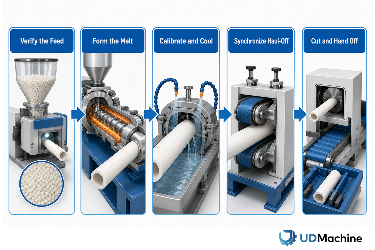
The sequence describes control rather than counts of physical stations. That control sequence starts at the tube-line boundary defined above and excludes carbon filling and cartridge assembly; the extrusion production line workflow ties raw material identity and quality control records to accepted tube output. It consists of preparing the material, extruding it, calibrating and cooling it, haul-off, and cutting or perforating it. In reality, the various functions of an extrusion process may be subdivided into many stations. Conversely, two functions may be combined in one station.
An open-access Production Engineering study gives insight on the extrusion of thermoplastic granules. The study outlines how the granules are melted, passed through a die, calibrated, and then cooled and cut to the desired length. The study acknowledges that modularity of industrial extrusion lines allows for varied arrangements of the various components of the lines, and as such, a checklist of the components of an extrusion line does not necessarily specify the physical layout of the line.
- Verify the feed — match the resin grade, lot, additives, drying or conditioning state, and approved regrind rule to the trial record.
- Form the melt — stabilize feeding, melting, pressure, and die or mandrel alignment without treating one temperature as a universal recipe.
- Calibrate and cool — hold the tube geometry while removing heat, then record where collapse, ovality, or surface marks first appear.
- Synchronize haul-off — coordinate puller speed with extrusion output because drawdown can change bore, wall distribution, and final diameter.
- Cut and hand off — control length and edge condition, then assign perforation, cleaning, inspection, or downstream assembly to a named owner.
One documented oriented-PVC line in a separate Journal of Intelligent Manufacturing study included drawing, inline measurement, a cutter, and nine cooling or conditioning steps. It is not a UDF specification, but it is strong counter-evidence to any claim that all plastic tube lines share five physical stations.
Results cross-link this equipment with pipe making machine, UPVC drainage lines, and PVC double wall corrugated pipe machinery. Those are adjacent plastic machinery categories, not substitutes for a UDF plastic tube production line. Continuous extrusion of plastic tubes is the shared process family. Tooling and downstream uses, in combination with material characteristics, dimensions and quality, define the final product.
The studied industrial line was about 55 m long and reported a material-input-to-cutter lead time of 15-100 min, depending on pipe dimensions. Those values cannot be transferred to a UDF tube line; they show why station count, residence time, and response delay must be confirmed on the configured machinery before an operator changes a second variable.
Plastic Material and Melt-Window Controls
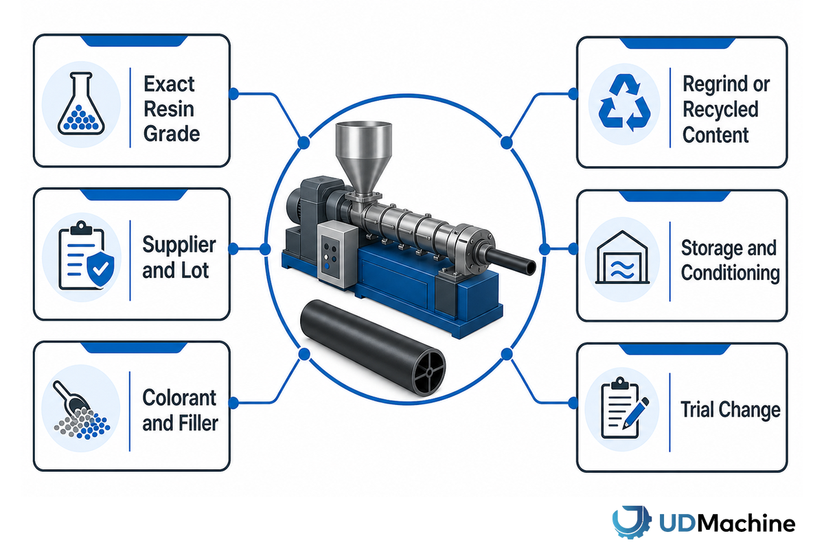
A processing recipe can’t be expressed in terms of just a PVC or PP resin. Those five process functions only become reproducible when the approved material identity and condition are fixed. Resin grade, supplier, lot, and the molecular and flow properties of the material can affect how the resin is processed. So can the method and state of conditioning of the resin, recycling and regrind rules, colorants, fillers, and thermal history.
The final plastic tube dimension is also not the die-channel dimension. A PlasticsToday die-design review explains that drawdown, cooling, and non-uniform thermal response alter the extrudate after it leaves the tooling. US Patent 4,882,104 likewise ties measured wall thickness to controlled adjustments, supporting feedback-based control without proving that every UDF machine uses that patented arrangement.
| Item to freeze | Why it matters | Evidence to retain | Do not infer |
|---|---|---|---|
| Exact resin grade | Flow and thermal response differ within one polymer family | Supplier data sheet and grade code | “PP” alone defines the melt window |
| Supplier and lot | A process comparison needs traceable material identity | Lot certificate and incoming record | A new lot is automatically equivalent |
| Colorant and filler | Additives can change viscosity and cooling behavior | Approved formulation revision | The base-resin setting remains valid |
| Regrind or recycled content | Thermal history and blend variation can change response | Permitted source, ratio, and blend record | Any available reclaim can be substituted |
| Storage and conditioning | Feed state can affect stability and visible defects | Storage condition and preparation record | A sealed bag proves identical condition |
| Trial change | Several simultaneous changes hide cause and effect | Timestamp, changed variable, response delay, and sample ID | The last change caused the first observed result |
An illustrative development record might hold one material lot, change one controlled variable, allow a buyer-defined 30 min observation window, and retain samples at 10 min intervals after a separately recorded 2 h warm-up. Those times are documentation examples, not recommended settings. The actual recommended waiting period depends on the tested line’s residence time and thermal response, not a generic heat-sink condition.
The 3-Part Bore-Wall-Edge Triangle Framework
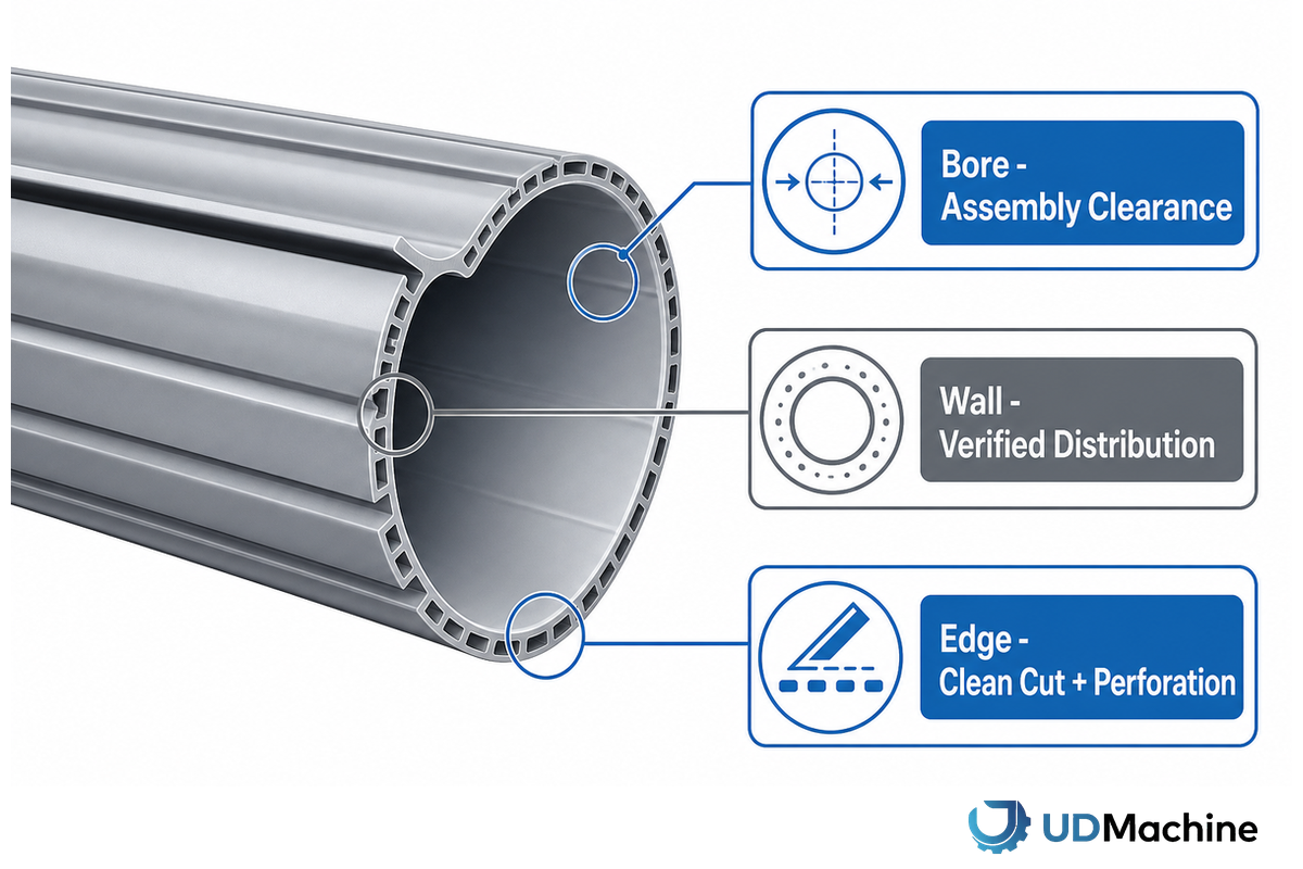
The Bore-Wall-Edge Triangle is an acceptance model made up of three aspects. Assembly clearance is governed by bore fit. Uniform wall thickness depends on verified distribution, not precision at one point. Edges governed by cut or perforation need to be clean. One final outside diameter (OD) measurement can’t represent all aspects of the triangle. Nominal tooling dimensions can’t replace measurements on conditioned samples.
ISO 3126 provides a general method context for measuring plastics piping components, while ASTM D2122-22 publicly identifies diameter, out-of-roundness, wall thickness, length, and straightness among its measured properties. Neither public scope creates a UDF-specific tolerance; acceptance values still belong in the buyer-supplier drawing or product specification.
| Feature family | Measurement type | Evidence to record | Downstream consequence | Limitations / not suitable for |
|---|---|---|---|---|
| Bore | Inside diameter | Location, axis, instrument ID, 0.01 mm example resolution | Fit over the mating feature | One location cannot show taper |
| Bore | Ovality | At least 2 axes at each stated station | Variable assembly clearance | Instrument force can distort thin walls |
| Bore | Straightness or bow | Support condition and measured span | Assembly alignment | A short sample may hide long-span bow |
| Wall | Minimum local thickness | Clock position and 0.02 mm example resolution | Local stiffness and perforation margin | Average wall can hide a thin sector |
| Wall | Wall distribution | Multiple clock positions and section ID | Centering evidence | Cut angle can bias a section |
| Wall | Surface condition | Lighting, side, distance, and defect rule | Handling and inspection consistency | Appearance alone does not identify root cause |
| Edge | Cut squareness | Fixture, reference face, and angle method | End-cap seating | Length alone cannot show squareness |
| Edge | Burr or chip condition | Inspection magnification and defect definition | Cleanliness and handling | A visual pass is not a particle-count result |
| Edge | Perforation exit edge | Tool direction, hole side, and retained sample | Flow path and media support | Open-area percentage cannot describe edge quality |
Engineering note
Instrument resolution isn’t measurement capability. The method also needs calibration traceability, fixture and operator controls, repeated checks, and an uncertainty basis suitable for the buyer’s tolerance.
ISO 1:2022 defines 20 °C as the standard reference temperature for geometrical product specifications and verification. That reference does not mean every UDF sample must be accepted at one universal condition; the drawing and agreed method must state the actual conditioning and reference basis used for comparison.
Perforation, Open Area, and Edge Quality
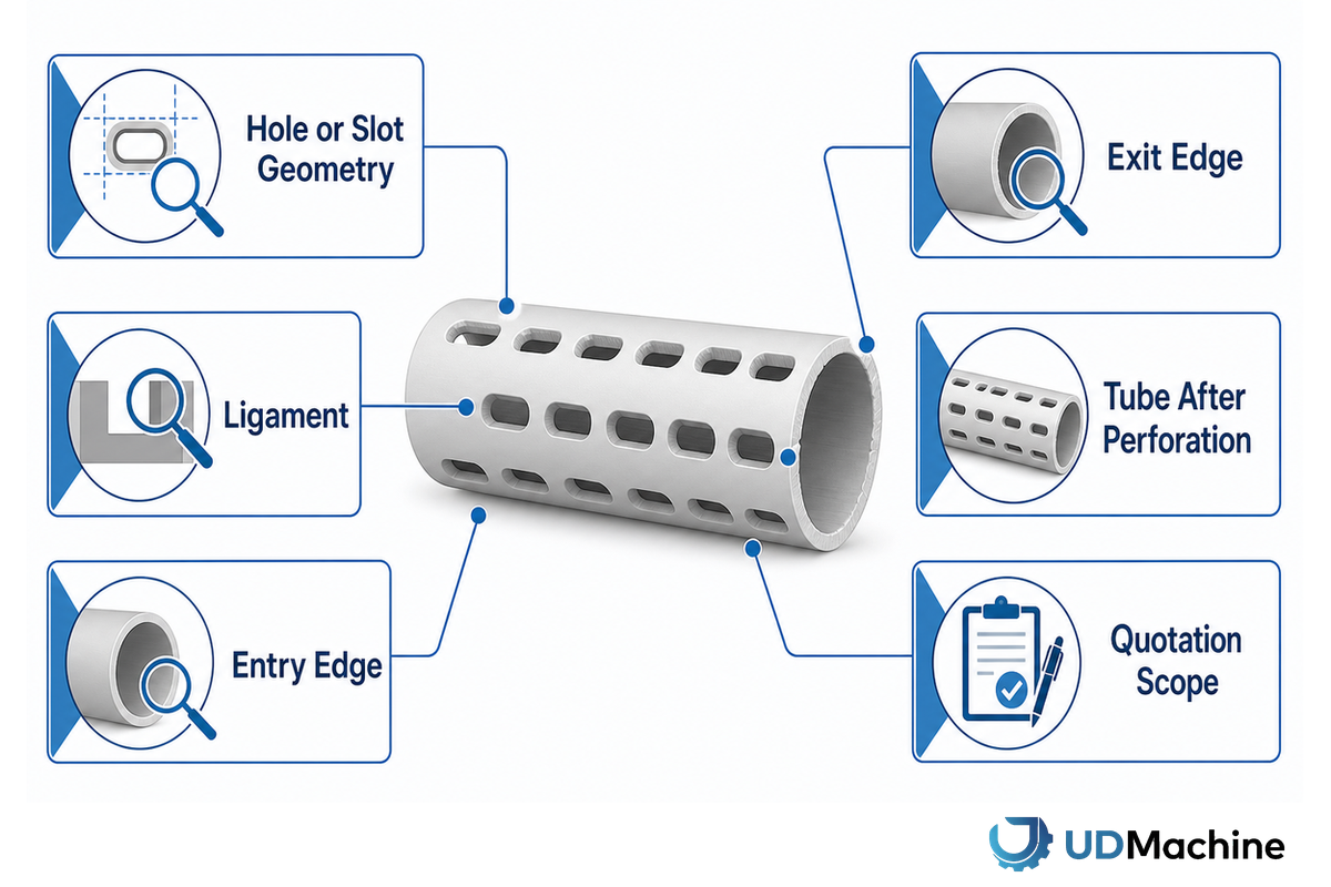
Quality of a perforated element is determined by a number of factors including shape of the hole or slot, ligament width, pattern of the element, condition of the wall, burrs, chips, cleaning, and support. This extends the Bore-Wall-Edge check from measured dimensions to the cut and perforated edge. Consequently, two perforated elements may have the same open area, but the component having the more useful function may not be apparent.
EP0873171B1 shows how a center support tube resists collapse in a cartridge architecture. This patent considers another type of filter, and thus defines the mechanical function of a support tube, but does not define a UDF material, pattern, or limits. NSF’s public overview of NSF/ANSI 42 also applies to finished filtration systems, not to certification of the tube-making machinery.
| Condition | Review | Evidence | Do not assume |
|---|---|---|---|
| Hole or slot geometry | Shape, orientation, and drawing revision | Dimensioned drawing and retained sample | Equal area means equal support |
| Ligament | Material remaining between openings | Measurement method and locations | Nominal pitch proves local margin |
| Entry edge | Tooling mark and raised material | Defined lighting and magnification | One side represents both faces |
| Exit edge | Burr, breakout, or loose chip | Defect rule and cleaning record | Cleaning corrects damaged geometry |
| Tube after perforation | Ovality, cracking, or local collapse | Before-and-after dimensional record | Pre-perforation dimensions remain unchanged |
| Quotation scope | Included station, tooling, chip extraction, and inspection | Signed scope and acceptance test | Every tube extrusion line includes perforation |
No primary UDF study in this run has supported a universal open area target. Customers should consider perforation a drawing-controlled work operation and evaluate whether the quoted machinery covers chips, tooling, post-perforation cleaning, and inspection. Also, finished filtration claims should be supported by completed finished-system documentation, not a machine certificate.
The 12-Row Symptom-Cause-Check Trace Matrix
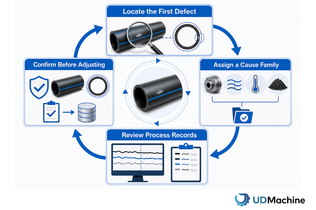
The Symptom-Cause-Check Trace rule allows an initial assessment of a defect by identifying the first location where the defect occurs, assigning a potential cause to the defect, and reviewing process records, and performing a check before adjusting process settings. That check begins where the preceding section ends, with an observed edge or perforation symptom rather than an assumed cause. Defects can occur due to material, tooling, process cooling, haul-off, cutting, perforating, measurement, and handling.
The BYU-Idaho extrusion troubleshooting text also uses process causes to classify defects. A Plastics Technology tubing-control article supports process adjustment based on measurement and explains the relationship between process variables and process controls.
| Symptom | Probable cause family | Record to review | Confirmation check | Limitations / do not assume |
|---|---|---|---|---|
| Wall thick on one side | Die or mandrel centering | Tooling setup and wall map | Measure multiple clock positions | Do not change all heat zones first |
| Tube oval after cooling | Calibration, cooling, or handling | Bath conditions and support points | Compare die-exit and post-bath axes | Do not blame the die from one late reading |
| Bore gradually shrinks | Melt output, drawdown, or cooling drift | Pressure, speed, and time trend | Plot readings against line timestamps | Do not use one sample as a trend |
| Diameter changes at constant puller display | Feed or melt-output variation | Material lot, feeder, pressure, and drive log | Verify actual rather than displayed speed | A steady display does not prove steady output |
| Repeated surface streak | Material contamination or tooling surface | Lot, cleaning, and changeover record | Mark streak position and inspect the flow path | Do not call every streak moisture |
| Random bubbles or voids | Material condition or entrained gas | Storage, preparation, and feed record | Compare a controlled material sample | Do not infer the cause from appearance alone |
| Tube collapses in the bath | Thin wall, unsupported bore, or cooling load | Wall map and first-collapse location | Observe before, at, and after bath entry | A forum fix is not a qualified recipe |
| Cut length varies | Encoder, haul-off slip, or cutter timing | Length trend and drive alarms | Compare commanded travel with measured length | Do not correct length through melt temperature |
| End face is angled | Cutter alignment or tube restraint | Blade, clamp, and fixture record | Measure squareness against a stated face | Correct length can coexist with poor squareness |
| Perforation burrs rise on one face | Tool direction, wear, or support | Tool count and setup record | Inspect entry and exit faces separately | Open area does not grade the edge |
| Two inspectors disagree | Method, fixture, resolution, or operator effect | Instrument and method revision | Repeat a blind cross-check on the same samples | Do not average incompatible methods |
| Damage appears after transfer | Handling or downstream interface | Container, transfer, and time record | Inspect at the line exit and next station | Do not assign every late defect to extrusion |
A practitioner thread describes a thin-wall HDPE example with a 6 mm outside diameter and 5 mm inside diameter collapsing in a cold-water bath. Collapsing starts in a particular zone of the tube, so that location should be recorded. The example’s collapse zone, dimension, and suggested remedies aren’t provided as UDF settings. The example suggests checking tooling, internal support, process temperature, cooling, and haul-off before assigning a cause.
Build a Measurement Plan That Can Be Repeated
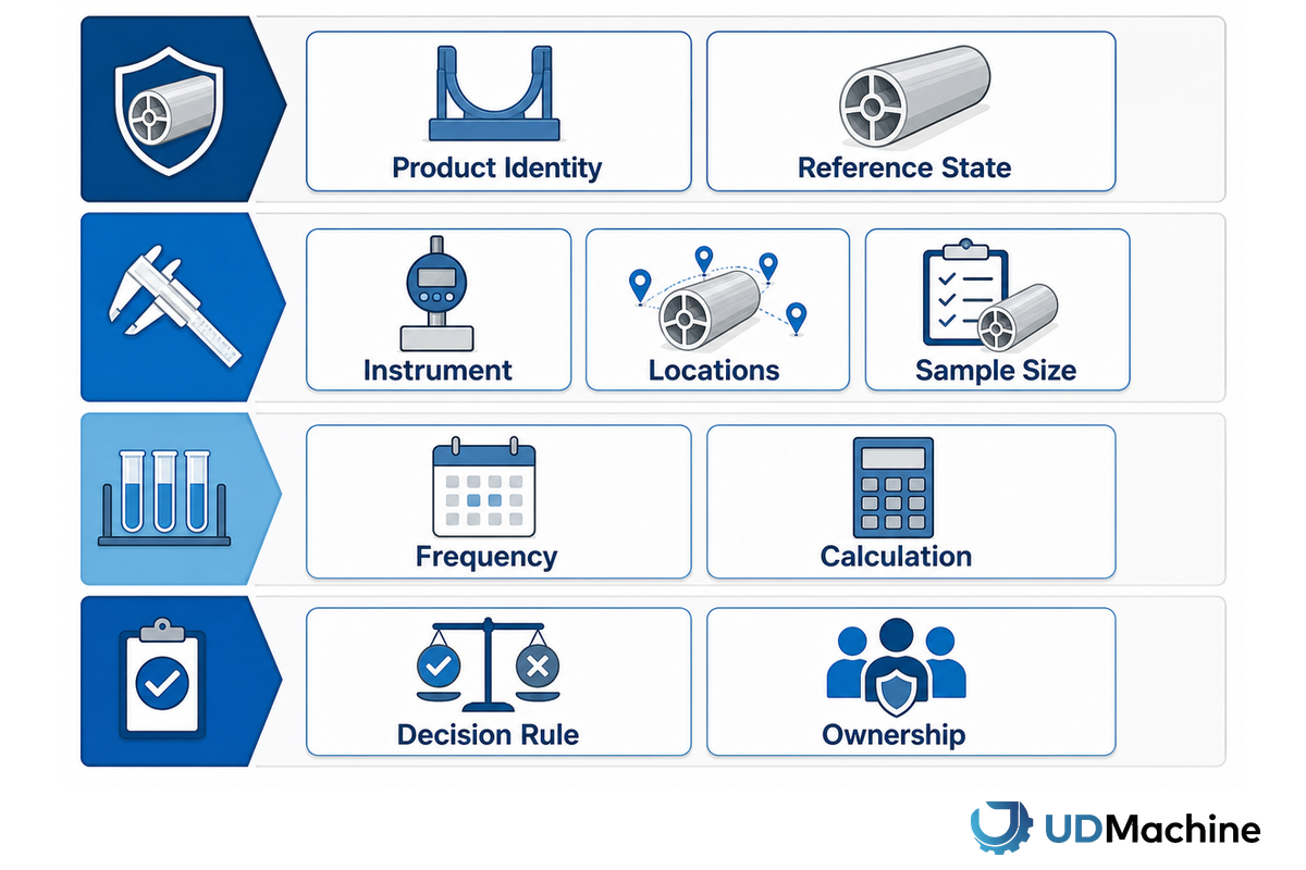
The measurand, sample, instrument, resolution, fixture, location, frequency, calculation, decision limit, nonconformance, and process adjustment are defined in a measurement plan. Two suppliers using the same material can still differ when process conditioning, positioning, and handling differ. Measurement, process adjustments, and nonconformance treatment should be performed according to a defined process plan.
According to the NIST process-monitoring handbook, samples should be defined by what’s measured, when and from what sample, how, and who performs the measurement. NIST identifies measurement-system effects from bias, repeatability, short-term and long-term variability, and other sources of variation, together with uncertainty, when evaluating a measurement system. Sophisticated display devices may give the illusion of a well-defined measurement process, due to the effects identified above.
| Plan field | What to state | Illustrative entry only | Why the field matters |
|---|---|---|---|
| Product identity | Drawing, material, lot, and process state | Drawing Rev B, one resin lot | Prevents unlike samples from being pooled |
| Reference state | Conditioning time and temperature | 20 °C reference, if the agreed method calls for it | Dimensions can change with sample state |
| Instrument | ID, range, resolution, calibration status | 0.01 mm display resolution | Makes the method reproducible |
| Locations | Axial stations and clock positions | 3 stations, 4 clock positions | Exposes taper and wall distribution |
| Sample size | Number and selection rule | 20 pieces selected through an 8 h trial | Defines what the data represent |
| Frequency | Time or production interval | One set every 30 min | Shows when drift could be missed |
| Calculation | Reported result and rounding rule | Minimum, maximum, mean, and range in mm | Stops selective reporting |
| Decision rule | Drawing limits and lot disposition | 100% inspected count kept separate from sampled status | Prevents sample acceptance from becoming a yield claim |
| Ownership | Recorder, reviewer, retention, and change control | Named buyer and supplier sign-off | Creates an auditable result |
The examples included in this document do not indicate any sampling plans or tolerance limits. Measurement uncertainty should be evaluated with respect to the tolerances. ASTM D2122-22 and ISO 3126 are measurement-method references; the applicable drawing or product specification supplies the dimensional limits. Dimensional limits for measurements are provided in the product/drawing specification.
A 20 °C reference state, a 0.01 mm display, and a 20-piece sample describe three different things: sample condition, instrument resolution, and sampling extent. All three describe parts of the method, but they don’t by themselves show that a measurement system is valid and capable.
How to Compare Supplier Trial Data Without Trusting a Headline Rate
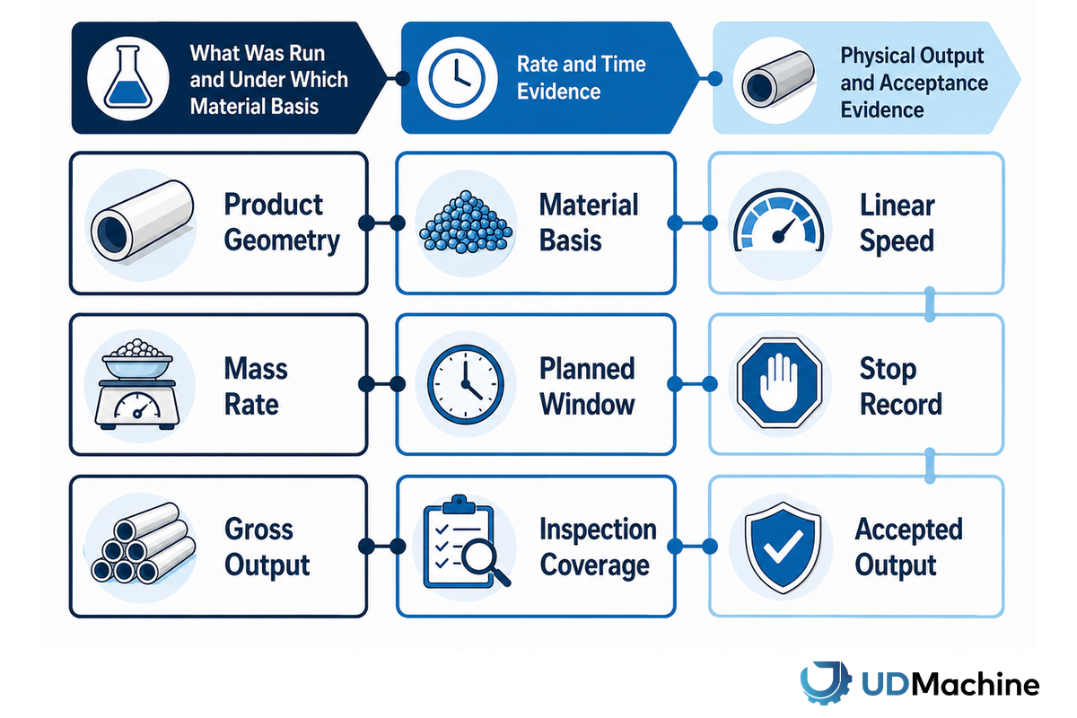
When the same product, process and operating conditions are compared, methods align and ‘capacities’ become meaningful.
Listings report incompatible estimates for this machine’s output. One lists approximately 50 kg/h. One market listing cites about 50 kg/h, while another seller snippet cites 0.6-0.8 m/min and 34 kW. These values aren’t directly comparable, as throughput, speed, and power are different values. The NIST acceptance sampling handbook notes the distinction of making a sampling decision versus estimating the true quality of the sampled lot.
ISO 2859-4:2020 covers procedures for assessing whether an audit population conforms to a declared quality level. Its public scope does not turn an accepted sample into a measured yield. A trial report should state whether every piece was inspected, a sample was used for lot disposition, or part of the output remained unmeasured.
Marketing labels such as “high efficiency,” “high efficiency UDF tube production,” and “efficiency UDF tube production line” don’t define a denominator or acceptance method. Therefore, a supplier can use those labels to describe production in terms of gross speed, mass rate, or by sample. Buyers should request labels be changed to witnessed quantities and an explanation of the inspection basis.
| Evidence type | Required label | Illustrative value | Decision use | Limitations / not suitable for |
|---|---|---|---|---|
| Product geometry | Drawing revision and dimensions | 6 mm OD / 5 mm ID example only | Defines what was run | Not transferable to another wall or diameter |
| Material basis | Grade, supplier, and lot | One PP lot for the full 8 h trial | Controls material identity | Not proof that other PP grades behave alike |
| Linear speed | Measured location and time basis | 0.6-0.8 m/min seller range | Shows travel rate | Cannot show mass or accepted pieces alone |
| Mass rate | Net material per operating hour | 50 kg/h seller claim | Shows mass throughput basis | Cannot compare without geometry and scrap |
| Planned window | Clock start and finish | 8 h planned period | Provides denominator time | Does not show actual running time |
| Stop record | Planned and unplanned minutes | 25 min planned / 18 min unplanned | Explains lost operating time | Reasons still need classification |
| Gross output | Meters, mass, or pieces made | 280 m produced | Records physical output | Includes uninspected and rejected material |
| Inspection coverage | 100% inspection or stated sample | 20 pieces from 280 m | Defines evidence coverage | A sample decision is not true-yield estimation |
| Accepted output | Fully inspected accepted quantity | 240 m accepted after 100% inspection | Supports accepted-output reporting | Do not claim this when only a sample was checked |
Comparison can be made between units of measurement that are observable to both parties. An example of this is expressing linear output as 240 m of fully inspected accepted tube over a period of 7.28 hours. This expression shouldn’t be used to predict the same output from another material, geometric configuration, or perforation pattern.
Integration and Safety Boundaries

Integration limits define the responsibilities for power, cooling, controls, haul-off, synchronization of cutters, guarding, isolation, finishing, and downstream carbon control. The trial-data boundary above becomes an interface boundary here, so each claimed rate must be tied to the actual utilities, controls, guarding, and downstream scope. Tube extrusion introduces concerns involving heat, motion, rotary equipment, nip points, cutting, electrical energy, and stored energy that must be addressed. Plastic finishing particles and combustible carbon dust require separate, process-specific assessments.
For US workplaces, 29 CFR 1910.212 addresses machine guarding, while 29 CFR 1910.147 addresses unexpected energization, start-up, and stored-energy release during covered servicing. Applicability and implementation belong to the employer and qualified site professionals in the actual jurisdiction.
“One or more methods of machine guarding shall be provided to protect the operator and other employees.”
A NIOSH workplace bulletin on microplastics notes that machining polymer products can generate dust and that high-energy or high-heat processes may release fine plastic particles. This 2020 bulletin is used here as dated screening evidence, not as a current exposure limit or a substitute for a site-specific industrial-hygiene review. Its finding does not prove exposure on every tube line, but it prevents perforation, drilling, trimming, or grinding from being dismissed without reviewing the actual method and controls.
An automatic machine label does not guarantee a complete site-ready system. Ask the manufacturer to customize only against a controlled drawing and interface list, then separate the CE marking evidence, warranty terms, after-sales service, and spare parts commitment from the technical trial result. Those commercial records matter, but none proves that the line can extrude the approved tube at an accepted rate.
Downstream carbon handling is a different boundary. OSHA’s combustible-dust guidance makes the concern conditional on the material and how dust is dispersed. NFPA 660 is listed as an active 2025 standard, but the need and method for a facility assessment depend on the carbon media, quantity, process, housekeeping, ignition sources, and local requirements.
Do
- Name the owner of each power, water, signal, guarding, and extraction interface.
- Verify actual connected load, voltage, frequency, and site protection for the configured line.
- Separate plastic-finishing particulate review from downstream carbon-dust review.
- Write isolation, restart, and contractor coordination into the site plan.
Don’t
- Treat a supplier’s machine demonstration as the employer’s site assessment.
- Assume a cutter or perforator is guarded because it appears inside the quotation.
- Claim every carbon material is explosible without material and process evidence.
- Use a machine certificate as proof of finished-cartridge filtration performance.
| Boundary | Supplier evidence | Buyer or site evidence | Release condition |
|---|---|---|---|
| Electrical | Load list, drawings, terminals, and control description | Available supply and qualified installation review | Interfaces match the configured proposal |
| Cooling | Required flow, temperature, pressure, and connection | Site capacity and water-quality basis | Stable supply under trial load |
| Controls | Signal list and sequence description | Upstream and downstream interface owner | Stops and interlocks witnessed |
| Guarding and isolation | Machine design and supplied devices | Employer procedure and site assessment | Qualified review before routine operation |
| Plastic finishing | Cutting or perforation method and extraction provision | Exposure review and housekeeping method | Actual process assessed |
| Carbon handling | Downstream equipment scope | Material and facility dust assessment | Separate media-handling basis documented |
A seller-stated 34 kW connected load is only a quotation input. It does not establish running demand, local supply suitability, protective-device selection, or the employer’s guarding and isolation duties. A configured interface schedule must replace the example before installation or site release.
Choose the Next UDF Manufacturing Conversation

The following discussion will cover the unresolved decision. Those routes follow directly from the unresolved line, safety, and downstream responsibilities documented above. This includes troubleshooting an existing tube defect, setting up a new tube production line, or assessing cartridge assembly downstream. Keeping those routes separate avoids asking an extruder quotation to answer a measurement problem, or expecting a tube machine to prove finished-cartridge performance.
- Diagnose an existing process: bring the approved material identity, drawing, time-aligned settings, sample locations, and the Symptom-Cause-Check Trace.
- Configure a tube line: bring the tube drawing, resin grade, required operations, utilities, interface list, inspection method, and witnessed trial basis to the UDF tube making machine page.
- Scope cartridge assembly: map carbon filling, separators, end caps, joining, and final testing through the filter cartridge assembly process.
Buyers who review multiple competing technologies can also consider the CTO carbon-block forming process. Even though both process options produce activated carbon cartridges, a CTO block extrusion process and a plastic tube support extrusion process are different production routes.
Define the Tube Before You Define the Line
Send UDTECH the drawing, resin grade, included operations, utility basis, measurement plan, and trial acceptance method. The response can then address a controlled UDF tube scope rather than a generic machine label.
Frequently Asked Questions
Q: What does a UDF tube making machine produce?
A UDF tube making machine forms the plastic support tube used inside a granular-activated-carbon filter cartridge. Its documented output should identify the resin, bore and outer dimensions, wall condition, cut length, and any included perforation or cleaning step; carbon dosing, separators, end caps, assembly, and finished-cartridge testing remain downstream unless the written scope expressly includes them.
The quotation should name the output state and next owner rather than relying on the word “line.” A seller’s 24 h running statement or 50 kg/h headline does not prove that the quote includes carbon filling, assembly, finished-system testing, or 24 h of accepted production. The tube-line acceptance record and finished-cartridge performance record answer different questions and should have different owners.
Q: How are tube diameter, wall thickness, and length changes reviewed?
Tube dimension changes are reviewed against the process function that controls them. Tooling and centering influence bore and wall distribution; haul-off and drawdown affect final dimensions; calibration and cooling influence stability; and the cutter controls length and end condition. Before comparing samples, freeze the resin grade, sample state, measurement locations, instrument resolution, sample count, and decision rule, then record the change against the approved drawing.
Trial one controlled adjustment at a time rather than translating the symptom into a universal temperature or speed correction. An illustrative record can identify a 20 °C reference state, a 0.01 mm instrument display, 3 axial stations, 4 clock positions, and samples every 30 min, but none of those placeholders is a UDF tolerance. Align every sample with the material lot and actual process timestamp, then compare it under the buyer-supplier method.
Q: What is the difference between a UDF tube line and a UDF cartridge assembly machine?
A UDF tube line forms, cools, pulls, cuts, and sometimes perforates a plastic support tube, while a cartridge-assembly machine begins with prepared components and may fill carbon, place separators, join end caps, and perform final cartridge operations. A complete route may need both scopes, but the word “line” does not prove that both are included.
The signed scope should identify the handoff state, interfaces, buyer-supplied work, and acceptance evidence for each machine group. A 0.6-0.8 m/min tube-rate statement, a 50 kg/h mass claim, or a 34 kW connected-load figure describes the tube-line offer only under its declared basis; none demonstrates carbon dosing, joining, or finished-cartridge performance.
Q: What causes uneven wall thickness in plastic filter tubes?
Uneven wall thickness can originate from die or mandrel centering, material or melt-output variation, non-uniform cooling, drawdown, haul-off behavior, or a measurement method that does not capture multiple clock positions.
Map the wall at stated axial and clock locations, align readings with material, pressure, temperature, cooling, and speed records, and confirm tooling position before changing several settings. A 0.02 mm display does not remove fixture or operator effects, and the same visible wall pattern can have more than one cause.
Q: Does a UDF tube extrusion line need a combustible-dust assessment?
A UDF tube extrusion line needs a process-specific review of its actual materials and operations, but plastic finishing particles and combustible carbon dust are separate questions. Cutting, drilling, grinding, or perforation may create plastic particles; downstream granular-carbon filling may create another dust scenario. The employer and qualified site professionals should review material properties, quantity, dispersion, ignition sources, extraction, housekeeping, and local requirements. Neither condition can be inferred from a machine name, supplier video, generic process description, demonstration, or certificate.
The assessment basis should identify which operations occur in the tube cell and which occur in downstream media handling, then assign each control and verification record to a named owner. Start with the actual resin, carbon grade, finishing method, transfer points, collection method, and facility layout. Review normal production, cleaning, jam clearing, maintenance, and foreseeable upset conditions separately. Record what the supplier provides and what the employer must complete. A 34 kW nameplate, 24 h operating statement, or enclosed appearance cannot answer the dust question. The result should be a site-specific decision supported by material and process evidence, applicable local requirements, and qualified review, not a universal claim that every tube or carbon operation is identical.
Related Articles and Equipment Pages
- UDF tube making machine configuration commercial owner for machine scope and quotation.
- Filter cartridge making machine families equipment hub for adjacent production routes.
- CTO activated-carbon production route contrast with plastic support-tube extrusion.
- Filter cartridge assembly process downstream filling, joining, and finishing handoff.
- Filter cartridge equipment due-diligence guide broader line-selection context.
Research and Scope Transparency
Before drafting, the research pass tested 30 related United States keyword histories. Of those, 26 broader media, cartridge, and extrusion terms had reportable demand, while the narrow UDF machine and production-line phrases did not. A separate inventory reviewed 71 live site URLs and reserved the existing commercial UDF solution page plus three dedicated UDF tools for their established roles, keeping this guide focused on process, quality, safety, and acceptance evidence.
Karry prepared this guide for Suzhou UDTECH Technology Co., Ltd. Technical statements were cross-checked against the linked government, standards, academic, patent, and trade sources. No first-party factory trial dataset was supplied for this article, so seller figures remain labeled, illustrative values are not specifications, and unverified certification, workshop-size, patent-ownership, award, or export-count claims are excluded.
References & Sources
- Overview of Drinking Water Treatment Technologies US Environmental Protection Agency.
- US Patent 8,167,141 B2 Google Patents.
- Data-model study for thermoplastics profile extrusion Production Engineering, Springer.
- Industrial oriented-PVC production-line study Journal of Intelligent Manufacturing, Springer.
- Die Design for Extrusion PlasticsToday.
- US Patent 4,882,104 Google Patents.
- ISO 3126 dimensional measurement scope International Organization for Standardization.
- ASTM D2122-22 dimensional test method ASTM International.
- ISO 1:2022 standard reference temperature International Organization for Standardization.
- EP0873171B1 center-tube patent Google Patents.
- NSF/ANSI 42, 53, and 401 filtration-system scope NSF.
- Extrusion Problems and Causes Brigham Young University-Idaho.
- What Makes for Perfect Control in Tubing Extrusion Plastics Technology.
- Elements of a sampling plan National Institute of Standards and Technology.
- Assumptions for measurement processes National Institute of Standards and Technology.
- Lot acceptance sampling National Institute of Standards and Technology.
- ISO 2859-4:2020 declared-quality assessment International Organization for Standardization.
- 29 CFR 1910.212, General requirements for all machines US Occupational Safety and Health Administration.
- 29 CFR 1910.147, Control of hazardous energy US Occupational Safety and Health Administration.
- Microplastics in the workplace National Institute for Occupational Safety and Health.
- Combustible Dust guidance US Occupational Safety and Health Administration.
- NFPA 660 standard development and edition status National Fire Protection Association.