Get in touch with Suzhou UDTECH Technology Co., Ltd. Company


Process control and factory acceptance guide
(Updated September 2026) | For production engineers, quality teams and technical buyers
The PP Melt Blown Filter Cartridge Machine is useful only when it repeatedly turns a declared polypropylene resin into cartridges that meet a declared output contract. One attractive sample, one short video or one pieces-per-day number does not show what happened during startup, steady operation, a restart or the end of a run.
Quick Specs for This Guide
Decision owned hereStable-output evidence, drift diagnosis and factory acceptance
Machine boundaryPP melt-blown cartridge forming through cut cartridge
Proof boundaryRun records, measurements and declared test methods
Not includedUniversal setpoints, model tables, prices or automatic certification
This document correlates process zones and interacting settings, and adds paired diagnoses and factory acceptance test cases. For scope, a quotation or other requests, please see the configured PP melt-blown filter cartridge machine solution.
Direct answer: Stable output is proved by binding resin, settings, time-ordered samples and six cartridge signals to one run, then separating equipment acceptance, process behavior and finished-cartridge conformity.
TL;DR
- A micron label needs a stated test method, fluid, flow condition and efficiency threshold.
- Resin, melt, air and collection variables must be read as a system.
- Small measured changes are not trustworthy until the measurement system is fit for purpose.
- Factory acceptance needs three tracks: equipment, time-ordered process evidence and cartridge conformity.
- A factory trial does not qualify performance at the buyer’s installed site.
1. Define the Output Contract Before You Discuss Setpoints
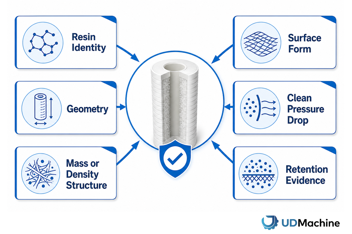
Start by defining the cartridge and the proof, not by asking for a temperature recipe. The contract should bind resin identity, geometry, mass or density structure, surface form, clean pressure drop and retention evidence to named methods, instruments, sampling positions and acceptance decisions.
A “1 micron PP filter” still leaves the rating basis, challenge particle, liquid, flow and removal-efficiency threshold open. Length, diameter, mass and structure must come from identified samples. Gross output requires a denominator to account for first runs, rejects and units that are removed for inspection.
Search results blend equipment and sales jargon. Meltblown is an alternate spelling of melt-blown. In the water filter industry, a 10 inch sediment cartridge is a format, not process proof. A carbon filter cartridge machine or CTO line, winding filter or yarn filter line for cotton, PP spun filter line, string wound filter cartridge line and membrane line are different categories. A filter cartridge offers useful performance only when its filter media is test-bounded. Claims such as pure polypropylene, diverse raw materials, customized solutions, commonly used in domestic and industrial service, or “equip every customer” remain commercial wording. Generic listings may call the collector a mold. Use the filter cartridge equipment selection and due-diligence guide for category comparison.
| Characteristic | Record or test | Owner | Cannot prove alone |
|---|---|---|---|
| PP resin | Grade, lot, certificate and feed condition | Buyer and supplier | Fiber or cartridge performance |
| Length and diameter | Declared points, instrument and tolerance | Product specification | Retention or pressure drop |
| Mass | Conditioned mass and calibrated balance | Quality team | Uniform density distribution |
| Wall or density profile | Agreed method and axial/radial locations | Joint test plan | A universal micron rating |
| Clean pressure drop | Fluid, temperature, flow, fixture and result | Test owner | Contaminant-removal efficiency |
| Retention claim | Challenge, method, efficiency and conditions | Application owner | Suitability for every liquid |
| Surface form | Plain, groove or other agreed finish | Purchase specification | Internal structure |
| Accepted output | Total minus exclusions, with time period | Signed FAT record | Long-run capacity at the installed site |
Evidence capsule: 21 CFR 177.1520 lists source-scoped polypropylene values including density of 0.880–0.913 g/cm³ and melting point of 160–180 °C. Those figures define part of a food-contact polymer rule. They don’t prove cartridge retention, machine capacity or finished-product compliance.[1]
2. Follow Five Evidence Zones From Resin Feed to Cut Cartridge

Even a stable-looking surface can hide drift that began several zones earlier. Trace resin feed, melt history, attenuation air, fiber collection and cartridge build as a linked route. For each of these processes and their flow regions, there must be control cards that define the response and the next point at which an operator adjusts a setpoint.
- Resin and feed: grade, lot, drying or handling condition, feed continuity and contamination.
- Melt and metering: extruder zones, melt pressure, heating response, screen condition and throughput.
- Air and attenuation: air temperature, pressure or flow indication, die condition and fiber behavior.
- Collection: die-to-collector geometry, mandrel rotation, axial advance, cooling and deposition pattern.
- Build and cut: outer diameter, wall structure, mass, length, surface, cutter condition and disposition.
“PP particles” is not a grade specification. Melt-flow behavior, molecular weight, additives and lot condition affect extrusion and attenuation. Preserve the melt record because throughput, pressure response and residence history can move while a heater display looks steady.
One air-pressure indication cannot describe the die field. The Collector builds diameter, wall, and density patterns as it advances. Cutting adds another boundary: sound forming can still yield variable length, crushed ends or loose fiber when the cutter or handling changes.
“The melt-blowing process involves high velocity airflow and fiber motion.”
Scenario: A surface becomes rough after a resin change. Before changing temperature, compare resin lots, feed, melt pressure, air, throughput and collection motion. The surface is a signal, not a proven cause.
Evidence capsule: one experimental study measured a maximum airflow range of 130–160 m/s near its die face. The result shows spatially intense, apparatus-specific airflow, not a setpoint for a commercial PP filter machine. Transfer the need to measure and compare, not the published number.[2]
3. Read Parameter Interactions, Not One Knob at a Time
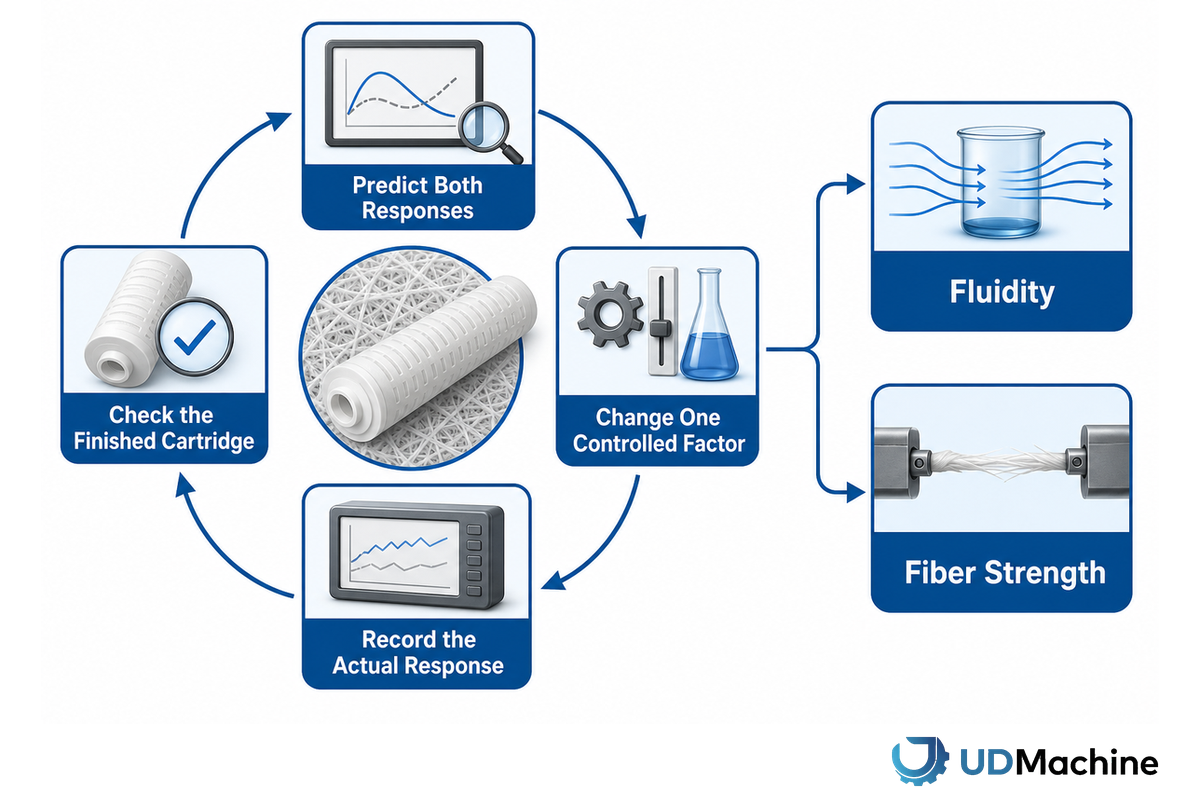
Each change has a first response and a tradeoff. One useful trial predicts both, changes one controlled factor or a planned combination, records the actual response and checks the finished cartridge. Visual fineness does not automatically mean stronger media, lower pressure drop or higher filtration efficiency.
A 2025 review describes the tradeoff: higher melt-flow index can improve fluidity, while lower molecular weight can reduce fiber strength. MFR is useful incoming-material data, not a replacement for melt strength or cartridge testing. Freeze the qualified grade and lot rather than asking a China manufacturer for the highest MFI.[3]
| Variable category | Primary response to watch | Second-order tradeoff | Measurement | Not suitable for assuming |
|---|---|---|---|---|
| Resin grade and MFR | Melt flow and fiber formation | Melt or fiber strength | Certificate, lot and qualified trial | Higher is always better |
| Feed continuity | Throughput consistency | Melt-pressure and mass variation | Feed and pressure trend | A temperature fault |
| Barrel and die heating | Melt condition | Thermal history or degradation | Actual sensors and material response | Displayed value equals melt uniformity |
| Polymer throughput | Material delivered per time | Fiber attenuation and cartridge mass | Metered rate and accepted mass | High output equals good output |
| Hot-air condition | Attenuation behavior | Fiber breakage, cooling or deposition | Air trend plus cartridge signals | One pressure proves uniform air |
| Die-to-collector geometry | Cooling and deposition | Bonding, loft and surface condition | Recorded geometry and wall profile | One distance controls density alone |
| Mandrel rotation | Circumferential build | Density, porosity and pressure drop | Speed record and radial result | Rotation sets micron rating |
| Axial advance | Material distribution along length | Outer diameter and cartridge weight | Speed, diameter and mass by position | One endpoint sample represents the run |
| Cooling and environment | Solidification behavior | Bonding and dimensional response | Ambient and product observations | A universal room-temperature limit |
| Cutter and handling | Length and end condition | Loose fiber, deformation and scrap | Cut sample and reject record | A forming-process defect |
Published figures such as 35 kPa or 35 cm sometimes migrate between articles without the original polymer, die, collector and measurement context. This guide does not turn those lineage gaps into a recipe. Develop a product, describe what you want to measure, perform a design of experiments or a controlled trial, evaluate measurements and consider effects (both positive and negative) of the process. The direction of an effect may transfer; the number often does not.
Evidence capsule: a continuous-cartridge apparatus study reported examples at 175.0 and 87.4 kg/m³ and found that rotation and forward motion affected different product properties. Those densities belong to that apparatus. They support joint measurement of motion, diameter and mass, not a universal density target.[4]
4. Build The 6-Signal Cartridge Record
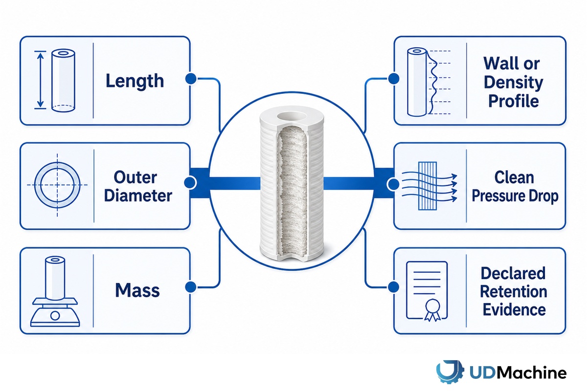
The 6-Signal Cartridge Record binds six finished-product signals to the same run and sample identity. It prevents a supplier from using one cartridge for dimensions, another for pressure drop and a third for retention while presenting the results as one coherent proof package.
The six variables are length, outer diameter, mass, wall or density profile, clean pressure drop, and declared retention evidence. Additional variables include resin lot, settings, sample time, process state, instrument, and disposition.
| Field | Record | Instrument or method | Measurement-system check | Disposition use |
|---|---|---|---|---|
| 1. Resin identity | Grade, lot, certificate, feed condition | Receiving and batch records | Identity and traceability | Separates material changes |
| 2. Setpoint snapshot | Actual resin, melt, air and collector values | Controller and independent checks | Sensor status and timestamp | Connects process to sample |
| 3. Length | Declared positions and result in mm | Qualified length method | Repeatability, bias and resolution | Geometry decision |
| 4. Outer and inner diameter | Locations, orientation and results in mm | Gauge and fixture | Operator and setup reproducibility | Fit and build comparison |
| 5. Mass | Condition and result in g | Balance and handling method | Stability and resolution | Material distribution signal |
| 6. Wall or density profile | Axial and radial locations | Agreed destructive or non-destructive method | Fixture, geometry and linearity | Structure comparison |
| 7. Clean pressure drop | Pa or kPa with fluid, temperature and flow | Qualified rig and fixture | Leak, zero and repeatability check | Hydraulic comparison |
| 8. Retention evidence | Challenge, efficiency, flow and method | Declared filtration test | Method suitability and controls | Claim-specific release |
| 9. Time and position | Sequence, process state and sampling point | Synchronized clock and sample ID | Traceability audit | Shows when drift appeared |
| 10. Decision | Pass, fail, hold, retest or investigate | Approved decision rule | Uncertainty or guard band near limit | Controls false acceptance and rejection |
Formatting example only, not a target: A at 0 min: 254.0 mm, 63.0 mm, 28.0 mm, 105.0 g, 8.2 kPa, 23 °C. B at 20 min: 254.1 mm, 63.1 mm, 28.0 mm, 105.3 g, 8.3 kPa, 23 °C. C at 40 min: 254.0 mm, 63.2 mm, 28.0 mm, 105.4 g, 8.4 kPa, 24 °C. D at 60 min: 253.9 mm, 63.1 mm, 28.0 mm, 105.2 g, 8.3 kPa, 24 °C. Snapshot fields may read 185 °C, 2.0 bar and 50 Hz. No value represents UDTECH capability or an acceptance limit.
Calibration status alone doesn’t show that the measurement process can distinguish real cartridge changes. NIST’s gauge-study guidance identifies repeatability, reproducibility, stability, bias, resolution and linearity as relevant issues. Fixture geometry, operator technique and sample compression can move a soft cartridge reading. Prove the measurement system is fit for the intended decision before interpreting small changes as process drift.[5]
Measurements close to a limit require agreement on a conformity decision rule. Record how measurement uncertainty is handled, including any guard band and the accepted false-accept or false-reject risk. A display with three decimal places is not three decimal places of certainty.[6]
Evidence capsule: this record deliberately joins measurements in mm, g, kg/m³ and Pa or kPa. Six signals plus material, settings, time and disposition create a 10-field trace. The units make unlike signals comparable by sequence, while the gauge study keeps instrument variation from masquerading as process variation.
5. Use The Paired-Drift Map Before Changing a Setting
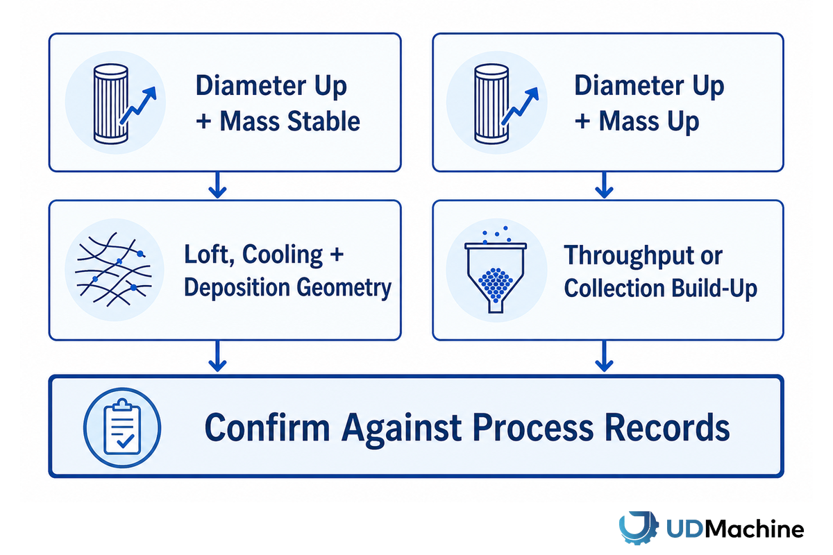
The Paired-Drift Map uses the joint direction of two cartridge signals to narrow the process family. It is a diagnostic screen, not a root-cause verdict. Confirm the suspected branch against resin, melt, air, collection and handling records before making a controlled change.
| Paired signals | Possible cause family | Record to review | Confirmation check | Unsafe shortcut |
|---|---|---|---|---|
| Mass ↑ + diameter ↑ | Throughput or collection build | Feed, melt pressure, rotation, advance | Wall profile by position | Reduce temperature blindly |
| Mass ↑ + diameter stable | Denser build or internal redistribution | Air and collection motion | Density profile and clean pressure drop | Call it higher capacity |
| Mass stable + diameter ↑ | Loft, cooling or deposition geometry | Air, collector distance and ambient record | Pressure drop and wall structure | Assume more material |
| Pressure drop ↑ + mass ↑ | Added material or denser structure | Throughput and collection motion | Geometry and retention method | Claim higher efficiency |
| Pressure drop ↑ + mass stable | Structure, bonding or flow-path change | Air, cooling, surface and fixture | Repeat rig check and profile test | Increase air immediately |
| Pressure drop ↓ + retention ↓ | More open structure or defect | Resin, air and collection record | Declared retention retest | Accept low energy consumption |
| Diameter variation + mass variation | Feed, throughput or axial-motion instability | Time trends and alarms | Order samples along the run | Average away the variation |
| One-end diameter ↑ + total mass stable | Axial distribution or traverse issue | Advance and position record | Measure both ends and center | Adjust total throughput |
| Color change + strength loss | Thermal history or contamination | Resin lot, heating and residence history | Material investigation | Ship after dimension check |
| Loose fiber + pressure drop change | Bonding, attenuation or handling | Air, collection, cutter and packing | Shedding and surface check | Blame the die alone |
| Dimensions pass + retention fails | Internal pore or method issue | Air, resin and test conditions | Method control and structure test | Release by appearance |
| Signals stable + rejects rise at cutting | Cutter or downstream handling | Blade, timing and transfer record | Inspect pre-cut and post-cut units | Retune melt blowing |
Do
Compare same-run signals, preserve sample order, check the measurement system and confirm the suspected zone against recorded changes.
Do not
Treat one visible symptom as one proven cause, change several knobs together or use an average that hides startup and restart behavior.
Scenario: Diameter increases, mass doesn’t change. Look at loft, cooling, and deposition geometry. Check for pressure drop and consult the air record before determining PP consumption. If diameter and mass increase, causes may include an increase in throughput or collection build-up.
Evidence Capsule: If there’s a 2 g increase in mass and a 0.5 mm increase in diameter, that provides more information than if either occurred separately. To completely evaluate the information, the gauge and product tolerance must be determined, as well as the running status of the product. The observed information allows a pair of checks to be performed; it doesn’t allow a machine adjustment to be made.
6. Freeze a Golden Run Without Calling It Universal
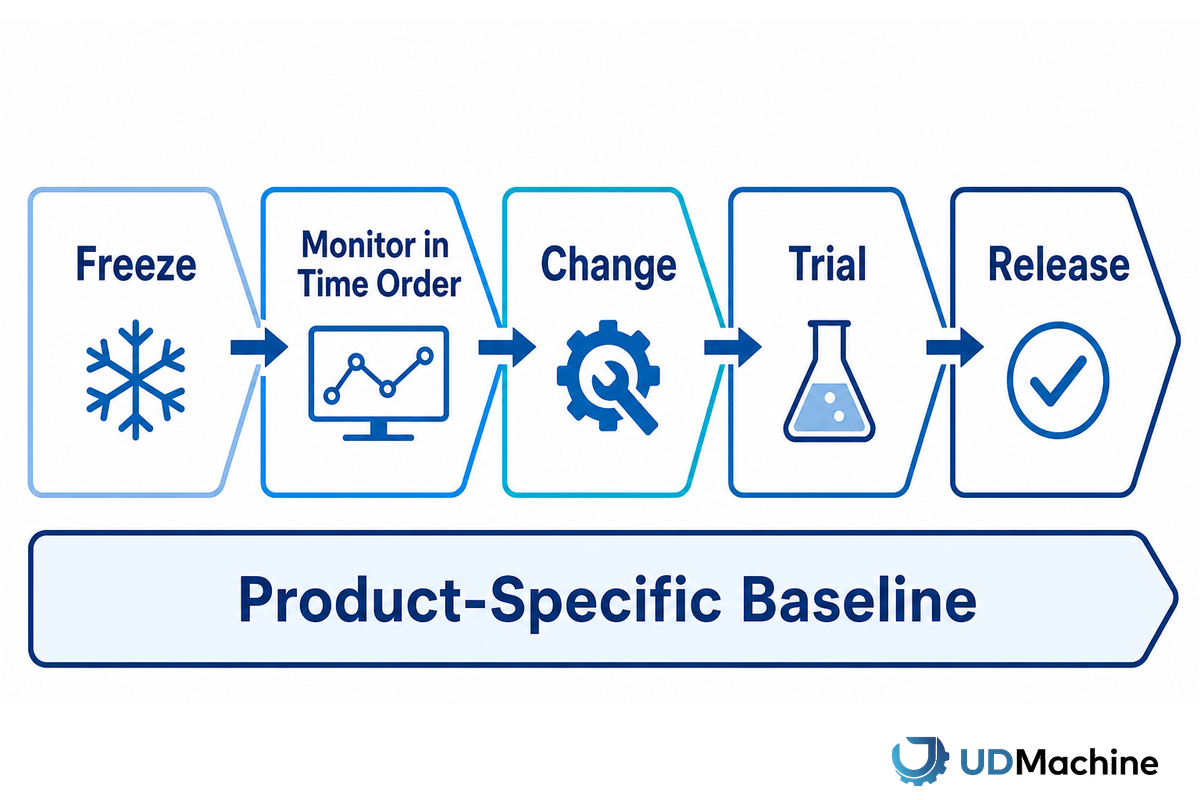
A golden run is a product-specific baseline with traceable limits. Bind it to resin grade and lot, cartridge geometry, instruments, test methods, machine configuration, approved ranges, sample sequence and release decision. Copies of a “Golden Run” may not be created for other mass or diameter values and retain the same definition.
- Freeze: identify the approved material, product, equipment configuration, method and version.
- Monitor in time order: keep startup, steady operation, interruption, restart and end-of-run samples in their actual sequence.
- Change: record what changed, why, who approved it and which signals could move.
- Trial: predefine the response measurements and comparison method.
- Release: decide against the declared contract, not against the most attractive sample.
Time order is necessary but not sufficient for a statistical claim of stability. NIST describes stability through consistent location, scale and distribution over time. Adjacent production observations can also be autocorrelated, which weakens the independence assumptions behind ordinary control charts and capability indices. Unless the duration and analysis support the claim, call the evidence an ordered run record, not proven process capability.[7][8]
Scenario: A 60-minute trial provides samples only at minute 55. Even if every sampled cartridge passes, the dataset says little about warm-up, a short stop at minute 25 or end-of-run behavior. Sample times should be stratified. Sampling times should be determined based on risk, method capability and decision intent.
Evidence capsule: one 60-minute run and one late sample can document a trial, but neither proves long-run stationarity. Statistical stability needs suitable duration, sequence and analysis, including dependence where relevant. The article therefore separates an ordered run record from a capability claim and preserves every restart event.
7. Link Maintenance and Calibration to the Signal They Protect
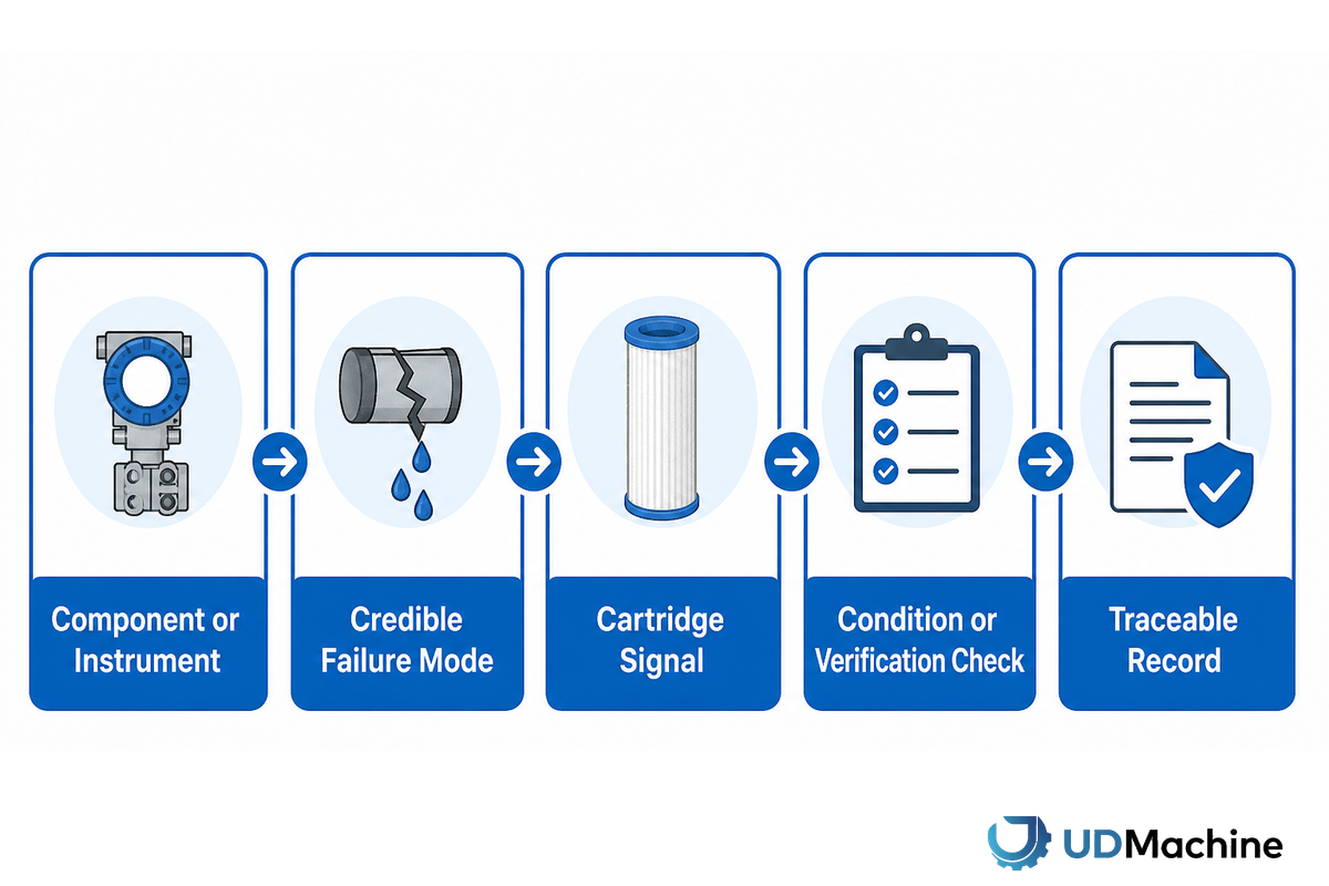
Calendar maintenance is incomplete when it is disconnected from product evidence. Link each component or instrument to a credible failure mode, the cartridge signal it can disturb, a condition or verification check and a traceable record. The appropriate interval depends on duty, design, history and qualified procedures.
| Component | Credible failure mode | Affected signal | Verification | Record |
|---|---|---|---|---|
| Feed system | Bridging, contamination, intermittent feed | Mass and diameter | Feed observation and trend | Lot, cleaning and event log |
| Extruder and screen | Wear, blockage or pressure instability | Mass, surface and color | Pressure response and inspection | Condition and replacement reason |
| Die or spinneret | Deposit, damage or unequal flow | Wall profile and surface | Approved inspection and cleaning | Finding and restored condition |
| Heaters and temperature sensors | Control or indication error | Color, strength and fiber behavior | Independent verification | As-found and as-left values |
| Air system and blower | Leak, restriction or changing response | Pressure drop and retention | Condition trend and air check | Alarm, service and condition history |
| Rotation and axial drive | Slip, timing or synchronization change | Diameter, mass and profile | Motion verification under load | Actual speed and intervention |
| Cutter | Wear, timing or poor support | Length, end condition and scrap | First-off and post-service check | Rejects and blade history |
| Inspection instruments | Bias, drift, fixture or operator effect | Any release measurement | Gauge study and check standard | Calibration plus suitability evidence |
NIST manufacturing prognostics work separates functional health from a bare asset-condition reading. Connect blower, heater and drive trends to cartridge signals, but don’t convert that principle into an invented weekly, monthly or annual service interval.[9]
8. Build the Factory Acceptance Test Around Good Output
A defensible factory acceptance test has three independent tracks: equipment and automation acceptance, time-ordered process evidence, and finished-cartridge conformity. Passing an interlock test does not prove filtration performance. Achieving one cartridge does not prove process control.
IEC 62381:2024 can inform scope, responsibilities and documentation for automation systems, but it does not certify a filter. NIST’s single-lot (n,c) plans address lot disposition through stated risks; they remain one-shot decisions, not long-run process control.[10][11]
| Track | Evidence item | Pre-agreed field | Result to retain | What it does not prove |
|---|---|---|---|---|
| A. Equipment and automation | Machine boundary | Included stations and handoff | Signed scope and drawing | Finished cartridge conformity |
| Safety and interlocks | Cause, action and reset | Executed test record | Site electrical approval | |
| Controls and alarms | Ranges, access and logging | Screenshots or exported log | Sensor accuracy by itself | |
| Mechanical operation | Rotation, advance, cutting and stops | Observed execution and exceptions | Commercial capacity | |
| Document handover | Drawings, manuals, spares, training | Revision-controlled register | Application validation | |
| B. Process evidence | Product and resin basis | Grade, lot, geometry and test basis | Traceable run header | Other resin or product grades |
| Startup boundary | When startup ends and why | Time and excluded output | Statistical stability | |
| Run duration and events | Agreed period, planned stops and restarts | Event-by-event timeline | Installed-site performance | |
| Stratified sampling | Startup, steady, restart and end positions | Order-preserving sample map | Independence of observations | |
| Output denominator | Total, startup, rejects, samples, accepted | Reconciled piece count | Future yield | |
| C. Cartridge conformity | Geometry and mass | Tolerance, points and instruments | Same-run results | Filtration performance |
| Pressure drop | Fluid, flow, temperature and fixture | Raw and calculated results | Retention claim | |
| Retention | Challenge, efficiency and method | Method-specific report | Every application | |
| Measurement decision | Gauge suitability, uncertainty and rule | Pass, fail or hold rationale | Zero decision risk | |
| Exceptions | Deviation, owner and disposition | Closed or open punch list | Unrecorded waiver |
Worked example: calculate accepted output, not headline output
Hypothetical inputs: 4,000 cartridges produced in the Lot; 160 start up cartridges; 80 process rejects; 40 cartridges removed for testing and/or holding.
Accepted output: 4,000 − 160 − 80 − 40 = 3,720 accepted cartridges.
First-pass accepted yield on the declared total: 3,720 ÷ 4,000 × 100 = 93.0%. State the denominator because another convention may treat sampled conforming units differently.
Illustrative conversion cost: if the documented run cost were $744, then $744 ÷ 3,720 × 1,000 = $200 per 1,000 accepted cartridges. These figures teach the arithmetic. They aren’t UDTECH capacity, cost or price claims.
One factory trial isn’t installed-site qualification. Utilities, resin handling, operators, downstream cap or groove work and normal interruptions can change the outcome. Map dependencies with the filter cartridge production planning guide, then plan commissioning and continued verification.
When not to buy or accept the trial
Don’t accept a trial when the resin lot is hidden, only the best cartridge is measured, samples are clustered after warm-up, planned stops are removed from the record, or rejected units disappear from the output denominator. Stop when the supplier changes several settings without a trial plan, quotes high output without accepted yield, or treats a clean pressure-drop result as a retention test.
Claims such as “automatic,” “high capacity,” “higher filtration efficiency,” “reliable,” “cost-effective” or “low energy consumption” need a test boundary and evidence. A video of a making machine running doesn’t supply either. Also reject a certificate bundle that confuses machine electrical approval, resin identity and finished-filter performance. None substitutes for the other. If the test method, instrument suitability, tolerance decision or open punch-list owner is unclear, record a hold rather than creating a verbal exception. A high-quality result is repeatable only when its basis remains visible.
Evidence capsule: the hypothetical run separates 4,000 total units from 3,720 accepted units and a 93.0% declared yield. That 280-unit difference is exactly why pieces-per-hour can’t stand alone. The arithmetic is reusable; the duration, sample plan, exclusions and acceptance limits must be project-specific.
9. Keep Machine, Resin, Cartridge and Site Evidence Separate
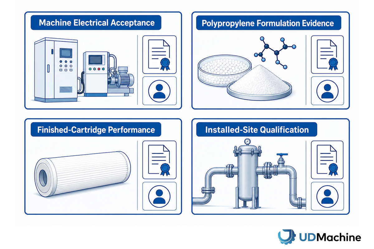
No single certificate should be accepted to demonstrate the production process is complete. Machine electrical acceptance, polypropylene formulation evidence, finished-cartridge performance and installed-site qualification belong to different owners and methods. Write the handoff between them so a valid document is not stretched beyond its actual scope.
| Evidence track | Question answered | Typical authority or method | Owner or handoff | Does not establish |
|---|---|---|---|---|
| Machine electrical | Is equipment acceptable under the applicable installation rules? | OSHA 29 CFR 1910.303 and acceptable approval routes in the US | Supplier, integrator and site authority | Cartridge performance |
| Automation FAT | Were agreed functions and interfaces tested? | Equipment-specific plan informed by IEC 62381 | Owner, buyer and vendor | Stable filtration output |
| Polymer and formulation | Does the actual material meet its declared regulatory or technical basis? | 21 CFR 177.1520 where applicable, supplier declarations and tests | Material supplier and application owner | Every additive, article or use condition |
| Cartridge conformity | Does the finished cartridge meet declared geometry, pressure and retention methods? | Product specification and qualified test methods | Manufacturer and buyer quality teams | Every liquid or system claim |
| Drinking-water reduction | Does a treatment unit meet a named health-effects reduction claim? | NSF/ANSI 53-2025 scope and certification route | System manufacturer and certification body | Machine certification |
| Installed-site performance | Does the process work with actual utilities, people, material handling and downstream steps? | Site acceptance, commissioning and continued verification | Buyer site with supplier support | Unrelated products or future changes |
For a United States installation, OSHA 29 CFR 1910.303 addresses examination, installation and use of electrical equipment and recognizes approval as part of acceptance. It isn’t a global shortcut and it doesn’t test a polypropylene filter. Project electrical requirements must be settled for the destination, utilities and authority having jurisdiction.[12]
Food, beverage, chemical and water applications also need claim discipline. Base-resin evidence under 21 CFR 177.1520 is conditional on the actual polymer, permitted additives, finished form, food type and conditions of use. NSF/ANSI 53-2025 addresses drinking-water treatment units and specified health-effects reduction claims; it is not a melt-blown machine certificate.[13][14]
Application release may also require chemical compatibility, extractables or binding, particle shedding, structural integrity and worst-case time, flow, temperature and differential pressure. If a brochure says the media has “chemical compatibility and is suitable” for strong acid or alkali, require concentration, exposure, formulation and test. “Widely used” is not evidence.
Forming is also not the final production boundary. End caps, adapters, welding, grooving, assembly and inspection may need downstream cartridge assembly and finishing equipment. Assign each interface before calculating labor, yield or line capacity.
Evidence capsule: the 2025 edition of NSF/ANSI 53 concerns treatment units and named health-effects claims, while 21 CFR 177.1520 includes polymer conditions such as 160–180 °C melting-point entries for polypropylene. Neither document gives a PP cartridge machine an automatic finished-product approval.
Choose the Next Technical Conversation
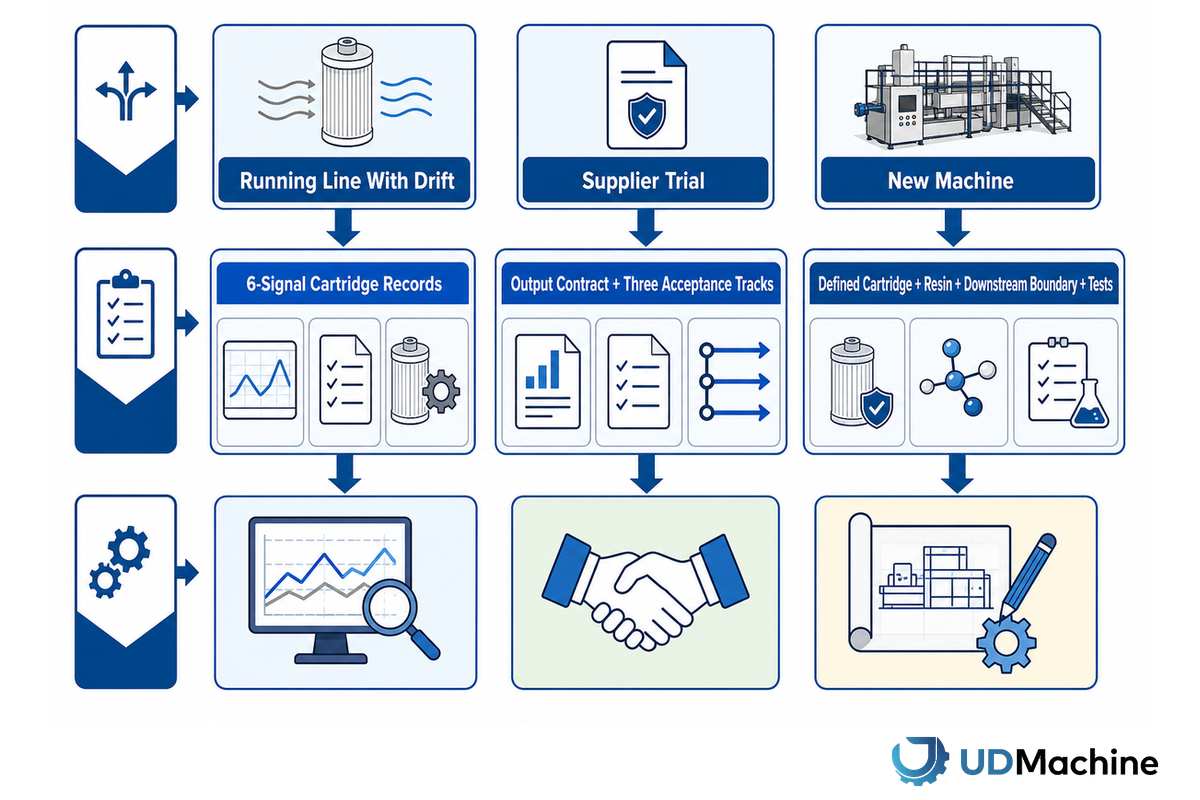
For a running line with drift, bring the recent 6-Signal Cartridge Records, event timeline and change history. For a supplier trial, submit the output contract and the three tracks of the acceptance sheet. For a new machine, take the defined cartridge, resin, downstream boundary and required tests to the PP melt blown filter cartridge making machine configuration page.
If you arrived through searches such as “PP melt blown filter cartridge machine price,” “PP melt blown filter cartridge machine parts,” or “PP melt blown filter cartridge machine for sale,” route configuration and commercial questions to the linked solution page; this guide remains focused on process control and acceptance evidence.
Decision rule
Do not ask whether a line can make a PP filter cartridge in the abstract. Ask whether the proposed line can produce, measure and document the agreed cartridge across a declared run, then repeat that evidence at the installed site.
Discuss Your Cartridge and Acceptance Plan
Frequently Asked Questions
What is a polypropylene melt-blown filter cartridge?
The polypropylene melt-blown filter cartridge is a cylindrical depth-filter element formed by attenuating molten polypropylene into fibers and collecting them in layers; its performance still depends on declared geometry, flow, pressure-drop and retention test conditions.
A polypropylene melt-blown filter cartridge is a depth-filter element formed by attenuating molten PP into fine fibers and collecting them into a self-supporting cylindrical structure. Its useful specification is more than a micron label. Geometry, mass or density distribution, clean pressure drop, test liquid, flow condition and the stated retention method affect what the finished cartridge can claim. The cartridge is the product; the forming machine itself does not inherit the cartridge’s filtration certification.
What is a PP filter cartridge?
The PP filter cartridge is a filter element whose declared media or structure uses polypropylene; that material label alone does not define construction, efficiency, pressure drop, chemical compatibility or service suitability.
A PP filter cartridge is a filter element made wholly or partly from polypropylene for a declared filtration duty. The category can include a melt-blown depth cartridge and other constructions, so “PP filter” does not by itself define pore structure, efficiency, removal rating, pressure drop or chemical suitability. Check the exact construction, materials, dimensions, end configuration, test method and operating conditions. A “pure PP structure” is a supplier claim that still needs material traceability and application review.
How does a PP melt blown filter cartridge machine work?
The PP melt blown filter cartridge machine melts qualified polypropylene, attenuates it with heated air, and collects the fibers on a rotating, advancing form before building the required cartridge geometry and cutting it to length.
The machine melts qualified polypropylene, meters it through a die, uses heated air to attenuate the melt into fiber, and collects those fibers while the cartridge form rotates and advances. Collection conditions construct the geometry and density profile before cutting. That explains the manufacturing mechanism but not the acceptance result. A buyer still needs the resin identity, setting record, same-run dimensions and mass, clean pressure-drop result and a declared retention test to show that the intended cartridge was produced.
Which machine settings control micron rating?
No single setting proves a micron rating.
Melt, air and collection settings influence fiber and pore structure, but no setpoint alone proves precision or a micron rating. Specify the cartridge, test fluid, flow condition, challenge particle and removal-efficiency threshold, then validate the claim with that declared method.
What should a PP filter machine factory acceptance test include?
The PP filter machine factory acceptance test uses one declared cartridge basis and keeps three proof tracks separate: equipment and automation acceptance, time-ordered process evidence, and finished-cartridge conformity.
Begin with the resin grade and lot, length, inner and outer diameter, target mass, surface form, pressure-drop method and retention method. Record the machine configuration, instruments, measurement-system suitability and the uncertainty decision rule where relevant. Define when startup ends, the run period, included stops and order-preserving sample points across startup, steady operation, interruption or restart and end of run. Report total output, startup scrap, process rejects, sampled units and accepted output separately. Keep equipment and automation acceptance, time-ordered process evidence and finished-cartridge conformity as three tracks. Retain settings, alarms, material certificates, drawings, manuals, spares, training and exceptions. A passing factory test does not prove statistical capability, performance after installation or suitability for every application. Site commissioning, continued verification and application-specific tests remain separate.
References & Sources
- 21 CFR 177.1520, Olefin Polymers, Electronic Code of Federal Regulations.
- Airflow Field and Fiber Motion in Melt Blowing, peer-reviewed open-access study.
- Polypropylene Materials and Melt-Blowing Review, peer-reviewed open-access review.
- Continuous Frame-Type Melt-Blown Filter Cartridge Apparatus Study, Machines.
- Gauge Studies and Measurement Issues, NIST/SEMATECH e-Handbook.
- Conformity Assessment Decision Rule, NIST.
- Process Stability, NIST/SEMATECH e-Handbook.
- Statistical Process Monitoring for Autocorrelated Data, NIST.
- Manufacturing Prognostics and Health Management, NIST.
- IEC 62381:2024, Factory Acceptance Test, Site Acceptance Test and Site Integration Test, IEC.
- Single Lot Acceptance Sampling, NIST/SEMATECH e-Handbook.
- 29 CFR 1910.303, General Electrical Requirements, US Occupational Safety and Health Administration.
- Drinking-Water System Component Health-Effects Scope, NSF.
- NSF/ANSI 53-2025 Drinking-Water Treatment Units, ANSI.
Method statement: sources include peer-reviewed melt-blowing research, NIST measurement material and US regulatory pages. Numbers stay source-bound. The 6-Signal Cartridge Record and Paired-Drift Map are decision aids, not standards, specifications or approvals.