Get in touch with Suzhou UDTECH Technology Co., Ltd. Company

Contact Form 使用中

Filter Cartridge Assembly & Finishing Equipment

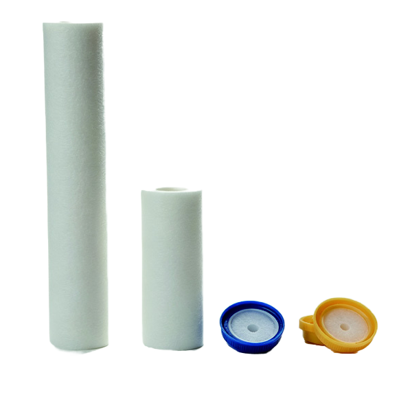
Filter cartridge equipment lines include post-forming stations for the carbon block or cartridge: wrapping, cap gluing or capping, heat-welded joining, handling, unloading, and final acceptance. UDMachine assists the buyer in turning the product prototype and target into an actual specification before automated machines are compared.

Send Your Cartridge Requirements
Filter Cartridge End Cap Gluing Machine Carbon Block Filter Wrapping Machine Filter Cartridge Assembly Process

Assembly Decisions Before Machine Selection

A functional proposal starts with what comes into the station and what needs to go out of the station. The project inputs, not general promises about each machine category, determine whether it is a stand-alone filter assembly machine or an assembly line, while ISO 12100 provides the framework for defining machinery limits before risk assessment.

Carbon rod or cartridge body, media or wrap, core, end caps, adapters, and adhesive or thermal joining route.
Finished dimensions, wrap overlap, end-cap position, seal condition, appearance limit, and rejected-part handling.
Measurable checks, sample quantity, method, instrument, decision rule, and responsibility at FAT.
Assembly Decisions Before Machine Selection

Assembly and Finishing Equipment Range

Use the equipment cards to open the corresponding product page. The process guide is represented in the same style of card, but it is labeled as guidance and not a model of the machine.

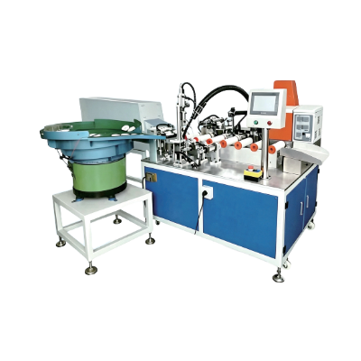
Filter Cartridge End Cap Gluing Machine

Filter Cartridge End Cap Gluing Machine

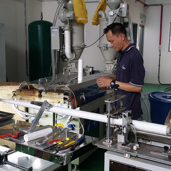
The cataloged fully automatic gluing and capping configuration combines carbon-rod ejection, non-woven wrapping, a heat-welded connection, and product discharge.

  • Electrical supply: AC220V/50Hz
  • Rated power: 2000W
  • Control: PLC+HMI
View Equipment
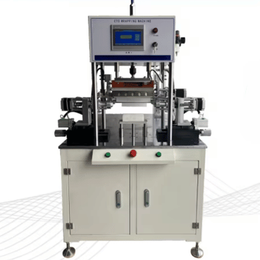
Carbon Block Filter Wrapping Machine

Carbon Block Filter Wrapping Machine

Define the wrapping station from the carbon-rod dimensions, wrap material, feeding and tension control, overlap, longitudinal joining method, cut position, and required discharge orientation.

The equipment page is the correct starting point for the current model and configuration discussion.

View Equipment
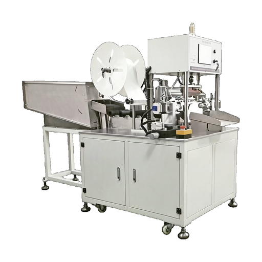
Filter Cartridge Assembly Process

Filter Cartridge Assembly Process

Map the sequence from the prepared cartridge through wrapping, cutting, end-cap fitting, fixturing, inspection, and final packing. Use it to identify which operations belong inside the automation scope.

View Process Guide
Configuration rule

The AC220V/50Hz, 2000W, and PLC+HMI values above apply to the shown full-automatic gluing and capping configuration. Those values are not interchangeable between one filter machine and another; final electrical, controls, tooling, and interface scope belongs in the project quotation.

Cartridge, Media, and Component Fit

Assembly equipment should be chosen from the physical stack-up. The product name “carbon block cartridge” does not define requirements for geometric tolerances, joining behavior, filtration, or handling at the station input, so these physical limits belong in the ISO 12100 machinery-boundary review.

  • O.D. and I.D., overall length, straightness, and end finish condition.
  • State whether the body is a carbon block, pleated pack, wound body, melt-blown body, or another construction.
  • Surface dirt, brittleness, temperature limit, allowed contact area with the clamp, and direction.
  • Wrap or non-woven specification, width, overlap, and joint requirement.
  • End-cap material, geometry, fit, adhesive or thermal joining route, and cure/cooling profile.
  • Joining compound, hole, net, gasket, adapter, valve, label, and packaging support.

Just because a cylindrical cartridge filter works for liquid filtration doesn’t mean it is interchangeable with a pleated filter cartridge, air filter, membrane element, micron-rated depth product, or high flow format. Different filter media, filter housing interfaces, and end geometries could mean you’ll require different tooling even when the finished products look similar.

Dust, bow, compressibility, and end variation can all be concealed by a nominal drawing. For a product that must be located, wrapped, capped, or discharged from the equipment without damage, also include a low, nominal, and high example.

Start with the parts the station must handle, then define the accepted cartridge. The machine boundary becomes much clearer when both ends of the process are visible. UDMachine Engineering Team.
Cartridge Media and Component Fit

Joining, Wrapping, and Finishing Routes

The correct route will vary with the cartridge construction and required seal. The common assumption that one joining method will always be the correct choice does not hold when materials, service fluid, geometry, and acceptance criteria vary, and the related hazards and risk-reduction measures should be reviewed under ISO 12100.

Patent literature documents adhesive potting, mechanical retention, ultrasonic welding, and other thermal fusion approaches, but those examples are not interchangeable with welding machine or filter machine specifications. The trade-off belongs in the product brief, not in a generic ranking of technologies.

Operation Buyer inputs Process variables Acceptance focus
Wrapping Rod diameter and length, wrap material and width Feed, tension, overlap, joining path, cut position Coverage, seam continuity, wrinkles, exposed area
End-cap gluing Cap geometry, cartridge end, adhesive system Dose, placement, insertion force, dwell, cure or cooling Position, bond continuity, leakage or pull requirement
Heat-welded connection Material pair and thermal window Temperature, pressure, time, cooling and fixture alignment Fusion continuity, deformation, alignment, seal condition
Trimming and cutting Finished length and edge condition Reference location, blade/tool route, dust control Length, squareness, burr or loose-fiber limit
Adapter finishing Adapter type, orientation and interface Insertion, joining, torque or position control Orientation, retention, gauge or functional check

A complete equipment proposal should identify which variables are controlled automatically, which are recipe inputs, and which remain operator checks, especially when several filter machines share one automated process flow.

14-Field Assembly and Finishing RFQ Matrix

Complete this form before comparing machine prices. A quotation based only on nominal size creates risk because tooling, sensors, handling, and acceptance depend on the actual product-size range, while the safety-boundary field supplies inputs for the ISO 12100 risk assessment.

Unlike a machine-name inquiry, the UDMachine 14-field matrix keeps product fit, interfaces, safety, and acceptance in the same conversation. The wrong choice is usually exposed by an unanswered field before equipment is released.

#RFQ field What to provide Why it changes the equipment
01 Incoming body Construction, material, sample, and condition Determines handling and process compatibility.
02 Diameter range Minimum, nominal, and maximum OD/ID Sets tooling, guides, clamps, and sensors.
03 Length range Minimum, nominal, and maximum length Sets support, cut, transfer, and discharge geometry.
04 Wrap Material, width, thickness, overlap, joint Sets feed, tension, joining, and cutting functions.
05 End caps Material, drawing, fit, orientation, variants Defines nests, positioning, and joining route.
06 Joining route Adhesive, heat welding, or another approved method Changes dosing, heating, guarding, dwell, and extraction.
07 Finished output Drawing, golden sample, and visible limits Defines the machine result and inspection points.
08 Good output Accepted units per shift and planned minutes Prevents gross cycle rate from masking losses.
09 Changeover Product families, batch size, target change time Changes tooling concept, recipes, and line balance.
10 Loading Manual, assisted, or automatic infeed Defines labor, buffers, sensors, and guarding.
11 Discharge Direction, elevation, buffer, reject route Defines the downstream handoff.
12 Utilities Voltage/frequency, air, extraction, environment Changes electrical and process-support design.
13 Safety boundary Destination, access, guarding, isolation, hazards Sets risk-reduction and documentation scope.
14 FAT evidence Measurands, samples, methods, instruments, decision rules Makes acceptance objective before equipment release.

Quote Scope and Project Cost Drivers

The most useful comparison begins with equal scope. The lowest quotation is not necessarily the lowest project cost when tooling, trials, automation boundaries, controls, documentation, packing, commissioning, training, or spares are handled differently.

  • Number of product families and the required size range.
  • Manual, automated, or semi-automatic feeding and unloading.
  • Adhesive handling, heating, extraction, cooling, or cleaning requirements.
  • Recipe control, traceability, inspection sensors, and line communications.
  • Product tooling, change parts, trial materials, and acceptance samples.
  • FAT, reports, destination documentation, packing, and shipment preparation.
  • Installation supervision, commissioning, training, and spare-parts package.
  • Buyer-provided services and interfaces include utilities, suction, adhesive, consumables, and the upstream pleating machine. They also include downstream packaging machines.
Quote Scope and Project Cost Drivers

Normalize before choosing the lowest number

Mark each line item as included, optional, buyer supplied, or TBD. The comparison becomes more valuable when suppliers quote against the same acceptance boundary.

Quality Control and FAT Evidence

Quality Control and FAT Evidence

IEC 62381 provides a formal context for factory and site acceptance testing. It helps define owner, buyer, and vendor responsibilities for those checks. Translate the required cartridge results into checklist items in the purchase specification, and include any safety-function checks identified through ISO 12100 where they belong in the FAT scope.

A seal can look complete and still need a measurable acceptance method. Define the product-specific result before the FAT sample is produced.

Finished length, cap position, wrap coverage and overlap, seam continuity, appearance, retention, leakage, or another functional result defined by the product.
Recipe values, alarm and interlock response, reject handling, changeover, cycle observation, utility conditions, and controlled recovery after a stop.
Sample plan, method, calibrated instrument where required, result format, uncertainty or decision rule, nonconformance treatment, and signatures.
Document the scheduled production time, run time, total output, accepted output, stop reason, and product configuration tested. NIST describes OEE as availability x performance x quality; good output capacity keeps each factor visible instead of hiding losses in one headline number or a misleading efficiency comparison with another filtration system.

Configuration and Delivery Workflow

The following sequence keeps product fit and acceptance visible before equipment release, including the machine limits needed for the ISO 12100 review before scope freeze. Actual business milestones are defined in the project quotation and contract.

Define the product

Share drawings, samples, materials, variants, finished limits, and the intended production schedule.

Map the process

Assign wrapping, joining, trimming, handling, inspection, loading, discharge, and operator work.

Freeze the scope

Confirm tooling, controls, utilities, interfaces, safety boundary, documentation, and buyer-supplied items.

Agree acceptance

Define samples, measurands, methods, instruments, decision rules, and the FAT result package.

When product variants differ in material, diameter, length, cap, or joining route, list each family rather than sending only one nominal sample.

Machine-Specific Documentation

Ambiguity in documentation imposes an acceptance risk because the buyer cannot determine which products, options, and tests the record covers, so the ISO 12100 risk-assessment record must stay tied to the identified machine configuration. Company certificates do not mention how the shipped machine configuration fits the project; UDMachine project documents must identify the machine and its boundary, while IEC 62381 distinguishes factory testing from testing onsite.

Configuration record

Machine name or model, product family, tooling, electrical and utility data, controls, interfaces, options, and buyer-supplied scope.

Technical file set

Layout, operating and maintenance information, electrical or pneumatic documentation, parts list, and destination-specific conformity documents where applicable.

Acceptance record

Test configuration, samples, measured results, alarms and interlocks checked, open items, and the agreed disposition.

Destination and machine boundary matter

In some cases, partly completed machinery and completely finished machinery may require different conformity documents. Confirm the destination, provided scope, and responsibility for assembly before placing the document name in the purchase specification.

Projects That Need a Different Scope

This article focuses on assembly and finishing after a cartridge body, carbon rod, or prepared media pack is available; it does not replace upstream media forming or the definition of a complete filter production line, because a project outside that boundary needs its own intended-use and limits review under ISO 12100.

Upstream production

PP melt-blown extrusion, activated-carbon block forming, wire winding, pleating, and UDF tube production require their own process and equipment boundaries. They should not be folded into an assembly brief merely because they are also industrial filter manufacturing operations.

Unsupported joining route

If the product requires a material, adhesive, welding route, cleanroom condition, or regulated validation package outside the confirmed configuration, treat it as a separate engineering review.

Unmeasurable acceptance

“Looks good” is not enough when seal, position, retention, leakage, or capacity determines product release. Define the check before equipment selection.

Undefined line ownership

If upstream feed, downstream buffer, rejection, extraction, utilities, or controls have no owner, the interface must be resolved before the station can be finalized.

Filter Cartridge Assembly Equipment FAQs

Provide the incoming cartridge construction, diameter and length ranges, wrap, end caps, joining route, finished drawing or golden sample, accepted output target, changeovers, loading, discharge, utilities, destination, safety boundary, and FAT checks. The 14-field matrix keeps these inputs together.

No. AC220V/50Hz, 2000W, and PLC+HMI are stated for the cataloged full-automatic gluing and capping configuration. The wrapping machine should be confirmed from its own current configuration and quotation.

Compare accepted units in a defined shift and product configuration. Separate planned minutes, availability, performance against the ideal cycle, and quality yield. A gross rate without stops, changeovers, or rejects cannot describe good output.

There is no universal choice. End-cap and cartridge materials, geometry, service fluid, temperature exposure, adhesive or thermal behavior, cycle target, cleanability, and acceptance method all affect the route.

Define the product configuration, sample quantity, measurands, method, instruments, utility conditions, run duration, stop and recovery checks, alarms and interlocks, decision rules, responsibilities, and the final result record. IEC 62381 is a useful reference for acceptance-test checklists and role allocation.

Potentially, but the size range alone is not enough. Compare component materials, cap geometry, wrap width, joining route, nests, guides, sensors, recipes, and the changeover target. Each product family should appear in the RFQ.

State the installation country, operator access, loading and discharge method, adhesive or heat hazards, dust or fume needs, guarding interfaces, emergency-stop boundary, energy-isolation expectations, and electrical supply. ISO 12100 and IEC 60204-1 provide useful design context.

Normalize tooling, trial materials, automation boundary, controls, inspection, FAT, documentation, packing, installation, commissioning, training, and spares. Mark each item as included, optional, buyer-supplied, or unresolved.

Start with a drawing, representative samples, the finished product requirement, and the 14-field RFQ matrix. UDMachine can then discuss the correct equipment page and configuration instead of forcing the project into a generic machine name.