Get in touch with Suzhou UDTECH Technology Co., Ltd. Company

Filter Cartridge End Cap Gluing Machine: A Comprehensive Guide to Process Control and Validation

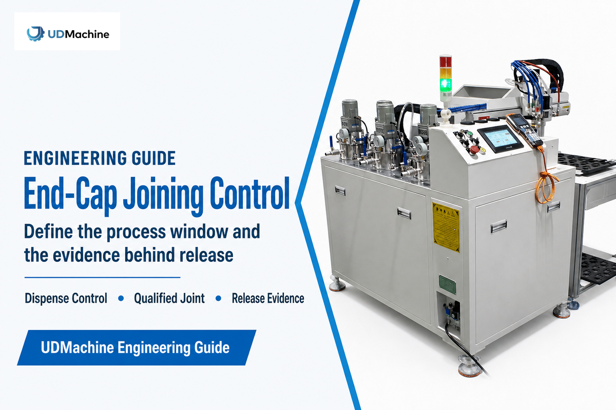
A filter cartridge end-cap gluing machine provides repeatability to automate both adhesive dispensing and end-cap assembly. It controls the feeding of the material, mixing, bead placement, motion, timing, temperature, alarms, and data pertaining to the recipe. The machine, alone, cannot prove that a finished filter satisfies retention, leak-tightness, pressure-life, sterility, or service-life challenges. These challenges would require specific bond evidence of the cartridge and a validated filter-level test.
Updated September 2026 · Written by Cherry · Reviewed for process and evidence boundaries
TL;DR
- Begin with the service environment and the cartridge material and geometry, along with the acceptance method – not a target cycle time.
- Choose polyurethane, epoxy, hot melt, reactive hot melt, or welding only after checking substrate compatibility and validation burden.
- Control surface condition, mix, dispense, assembly timing, bondline, cure, and traceability as one process window.
- Use the Five-level End-Cap Joining Evidence Ladder to distinguish machine records from the finished-filter proof.
- Keep FAT, FIT, SAT, and SIT separate to avoid confusing a supplier demonstration with qualification of the product.
What Does a Filter Cartridge End Cap Gluing Machine Actually Control?
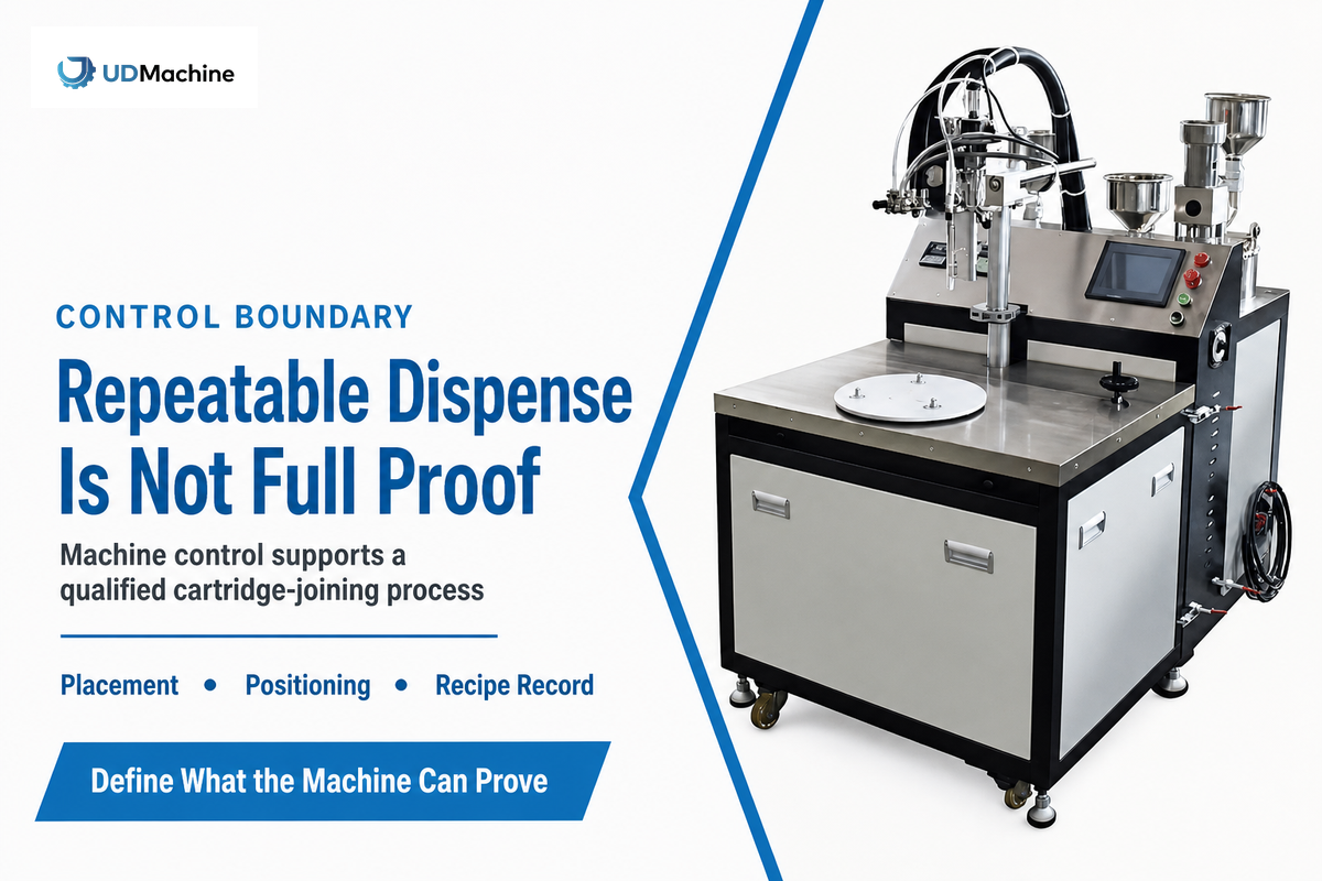
The machine’s basic function is easy to describe: place the correct amount of adhesive in the correct location, assemble the end cap within the approved time, and repeat the sequence. However, the overall task it fulfills is much larger. A two-component system may need separate material conditioning, proportioning, mixing, purging, and mixer-life control. A hot-melt system may need temperature management from the tank to the nozzle. The system must be capable of controlling the path of the bead and holding the cap in position, as well as controlling the adhesive application recipe, alarm setting, and documenting the process.
That piece of equipment is an integral part of the bonding process, but not the entire process. The machine doesn’t select an adhesive on behalf of the cartridge designer. It doesn’t eliminate mold release, oil, dust, or moisture from a contaminated cap. It is unable to make an incompatible plastic bond. It’s also unable to turn a filter-level integrity test into a valid retention claim unless the test has been correlated to the actual filter design and application.
Key boundary: a PLC green light doesn’t mean unmonitored interfaces are clean, that the bond cured, or that the finished cartridge will function properly. A green light may indicate that the monitored variables were within the limits of the program.
If you have drawings, materials, and a defined acceptance plan, the UDMachine filter cartridge end cap gluing machine solution page is the commercial route for discussing a configuration. This guide stays on the engineering side of that handoff: what to define and what evidence to request.
Start with the Cartridge, Not the Dispenser
The discussion of the equipment begins with the tasks and the duties. “We need a machine for 10-inch cartridges” isn’t sufficient. Two cartridges of the same nominal size can have different cap resins, media packs, support cores, engagement depths, gaps, surface conditions, service fluids, and release tests. Each of these variables can have an impact on the joining process and the required process window.
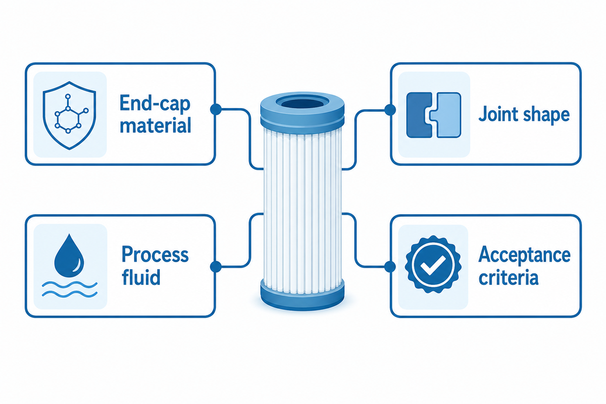
Build a controlled input pack around four questions:
- Identify the end-cap material, filter media, core or cage, any coating, potting contact area, and known mold-release or machining history.
- Describe the joint shape. Record engagement depth, radial gap, concentricity, allowable bondline, seating stop, and zones where squeeze-out cannot enter the flow path.
- State the process fluid, temperature range, pressure, cleaning chemicals, vibration, UV exposure, storage, sterilization, and cleanliness requirements that matter to the application.
- How will acceptance criteria be determined? Define the visual, dimensional, destructive, integrity, pressure, or other validated test that separates an accepted cartridge from a rejected one.
The 3M Structural-adhesive Guidance accounts for temperature, humidity, chemicals, loading, substrate, and process conditions interdependently, making several of these inputs selection criteria. It also states that a confirmed system should be evaluated on the materials and process rather than selecting from strength data.
“You should verify with testing that suggested pretreatments are effective with your specific substrates.”
The documents should go with the parts. If an adhesive has been chosen, provide the current safety data sheet and technical data sheet. When the adhesive has not been selected, say so. The grade, revision, storage condition, shelf life, lot identity, approved mix ratio, application window, and cure schedule must remain traceable.
There is no single “best glue” for a filter end cap. This includes dimensions for caps and bondlines in mm, mass of material in g, volume of dispense in mL, pressure in kPa, temperature in °C, open and cure time in s or min, connected load in kW, ratio tolerance in %, and limits of contamination in ppm, where the application defines them. The goal isn’t to give explicit values. Instead, it aims to prevent an unlabeled number from getting into the wrong recipe.
Adhesive or Welding? Use a Joining-Route Matrix
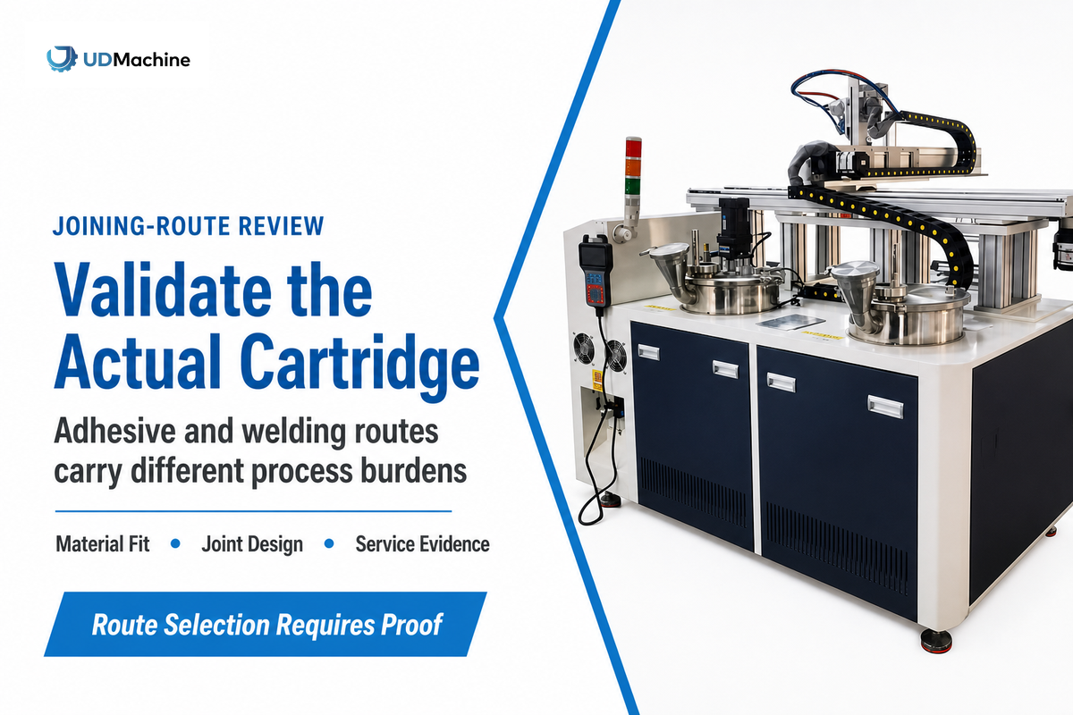
There’s no blanket statement that welding is automatically better or even cleaner, stronger or cheaper. The right route is the one that can be validated for the actual cap, media, joint, service environment, and production system.
| Route | Useful when | Process burden | Question that must be closed |
|---|---|---|---|
| 2K polyurethane | Toughness, flexibility, vibration tolerance, or gap filling is useful | A/B storage, proportioning, mixing, purge, work life, cure | Does the qualified grade bond both substrates through the full service envelope? |
| Epoxy | Strong bonds and chemical or temperature resistance are required | Ratio, mixing, cure, and formulation-specific rigidity | Can the joint tolerate peel, impact, thermal movement, and cure stress? |
| Conventional hot melt | Rapid handling and one-part automated dispensing fit the line | Melt temperature, hose/nozzle heat, open time, char and cleanup | Are substrate adhesion and service-temperature margins validated? |
| Reactive PU hot melt | Fast initial set plus later moisture reaction is useful | Moisture control, initial set, post-cure, heated delivery | Is the post-cure condition consistent through storage and release? |
| Ultrasonic or thermal welding | Compatible thermoplastics can form a clean joint without adhesive | Joint feature, tooling, fixture, energy/heat window, flash control | Are resin compatibility, media protection, and finished-filter integrity demonstrated? |
Ultrasonic welding needs thermoplastics that can soften and reform. A designed energy interface and adequate fixture support can help concentrate and transmit energy. Thermosets can’t be remelted in the same way, and not all thermoplastic pairs are compatible. Welding may remove adhesive contamination and cure time, but it adds joint-design, tooling, heat, flash, and media-damage concerns.
Adhesive bonding remains useful when materials are dissimilar, the joint needs gap filling, the parts are heat-sensitive, or weld energy cannot be delivered safely through the geometry. The choice should be made before the machine specification is frozen, because a metering-and-mixing line and an ultrasonic welder have different controls, utilities, maintenance, sample plans, and acceptance evidence.
Define a Measurable End-Cap Gluing Process Window
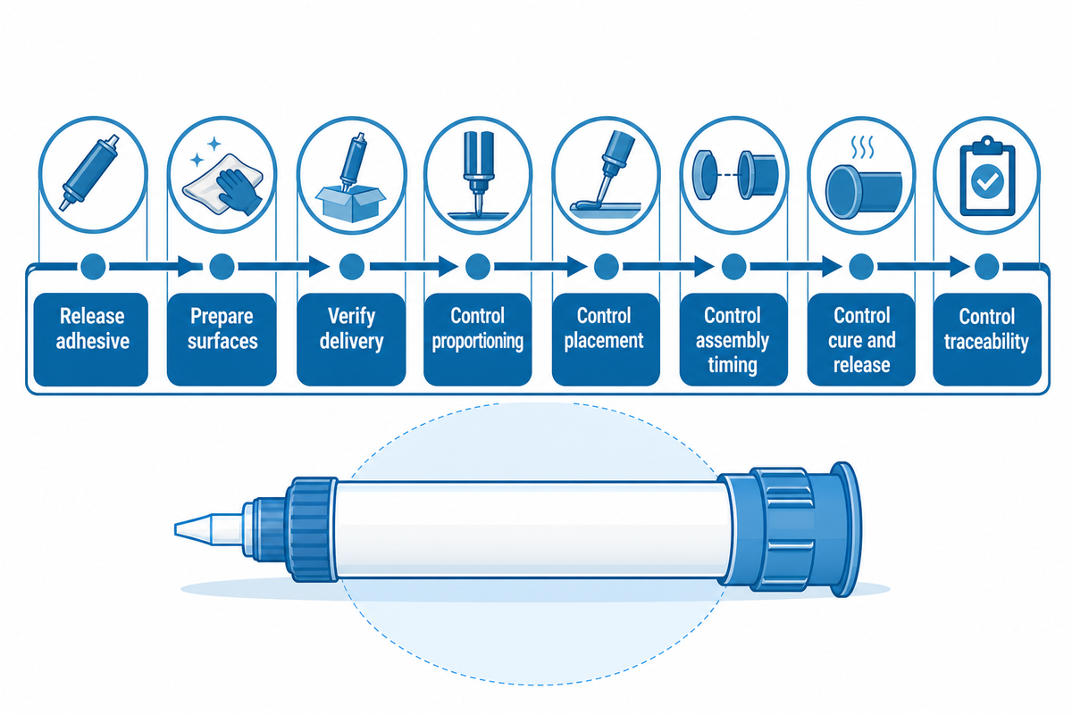
A recipe is more than a dispense mass. It’s a connected set of conditions that begins with material release and ends after cure. A stable process should define which variables are controlled directly, which are verified by a check, and which are inferred from a qualified setup.
- Release the adhesive. Confirm adhesive identity, lot, expiry, storage history, conditioning state, cap and media identity, and line clearance.
- Prepare surfaces: remove contamination with approved method, abrasion, chemical treatment, plasma, corona, or primer only as needed and as approved to satisfy material requirement.
- Prime and verify delivery: purge stale or separated material, install a qualified mixer, and ensure the mixed bead is uniform before production parts are allowed to enter the line.
- Control proportioning: For two-part systems, use the approved tolerance and ratio of the selected adhesive. Decide on the method of verification and how frequently the verification is done.
- Control placement: set mass or volume, bead path, start/stop overlap, nozzle position, motion profile, material temperature, and viscosity.
- Control assembly timing: seat the cap prior to the approved open time. Hold alignment, engagement depth and fixture conditions while the joint reaches handling strength.
- Control cure and release: record time and temperature basis, prevent premature movement and release only after the approved condition is met.
- Control traceability. Connect recipe version, material lots, operator, alarms, checks, rejects, rework, and acceptance results to the production lot.
Surface preparation deserves its own line item. 3M’s technical bulletin explains why a surface that looks clean can still require degreasing, abrasion, pretreatment, or a primer for a durable bond. It also warns that methods differ by substrate. That’s especially relevant when molded plastic caps carry release agents or when metal caps arrive with oil, coating, or oxidation.
Don’t include mix ratio, cure time, bondline or temperature from another adhesive in the equipment specification. These numbers should be tailored to the selected material and its qualification. The machine requirement should state range of operation, accuracy, verification method, alarm and record holding strategy to maintain the approved window.
The 5-Level End-Cap Joining Evidence Framework
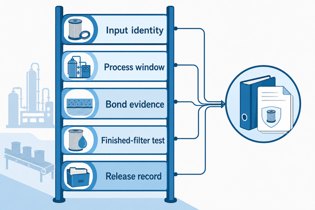
The most frequent acceptance error is combining five distinct questions into a single machine demonstration. The End-Cap Joining Evidence Ladder separates them.
| Level | Evidence question | Minimum record | Still not proven |
|---|---|---|---|
| 1. Input identity | Were approved parts and materials used? | Drawing/BOM revision, adhesive grade and lot, cap/media lot | Correct dispensing or cure |
| 2. Process window | Did monitored variables stay inside the approved recipe? | Ratio check, dispense check, time, temperature, alarms, recipe version | Bond integrity |
| 3. Bond evidence | Did the joint form as qualified? | Approved visual, section, coupon, hardness, peel/shear, or other bond check | Filtration performance |
| 4. Finished-filter test | Did the cartridge pass the defined product test? | Method, instrument, conditions, raw trace, limit, disposition | Every field-life condition |
| 5. Release record | Can the evidence be traced and changes controlled? | Lot genealogy, calibration, deviations, retest rules, release and change record | Performance after an unvalidated change |
A NASA bonding process specification isn’t a filter-cartridge standard, but it provides an excellent evidence model: surface condition, bondline control, cure conditions, records, and representative samples are treated as interconnected parts of a systematic bonding process. The specific numbers in that document aren’t hard filter limits; the important lesson is to bind the evidence to the same material and process conditions of production.
Filter integrity also needs careful wording. A peer-reviewed study of bubble-point-type tests found that method, instrumentation, membrane, and defect configuration affect sensitivity to defects. A passing bubble point wasn’t a direct measurement of bacterial retention. From a buyer’s viewpoint, the requirement is a published test procedure and validation of the specific cartridge, not an unexplained ‘PASS’ printscreen.
Treat the five levels as a way to organize evidence, not as a universal validation standard. For example, a general manufacturing cartridge and a sterilizing grade pharmaceutical filter may require different evidence of compatibility, cleanliness, integrity, retention, and the resulting documentation. The relevant standard, customer specification, and the regulatory framework will determine which tests are applicable and how evidence should be documented. Machine data, bond evidence, and tests on finished filters are all individual pieces of evidence, yet they should be examined together for the same released cartridge and its intended service.
Troubleshoot Bond Defects Without Chasing Setpoints
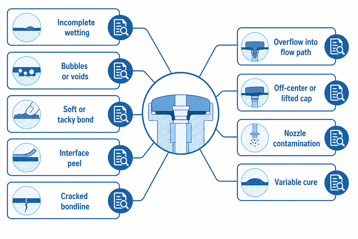
An increase in glue may not universally resolve the issue. This may conceal an underfill and create glue squeeze-out, longer cure, contamination, or a blocked flow path.
| Defect category | First checks | Containment before adjustment |
|---|---|---|
| Dry area or incomplete wetting | Surface contamination, low surface energy, bead interruption, low dispense, expired open time | Hold affected lot; compare surface and bead evidence; section representative samples |
| Bubbles or voids | Air during refill/mixing, incomplete purge, unstable feed, joint filling pattern, movement during cure | Freeze material lot and recipe; review pressure/temperature trends; examine sections before changing volume |
| Soft or tacky bond | Off-ratio mix, poor mixing, expired material, low cure temperature, early release | Stop release; verify ratio and mixed-bead condition; check actual part temperature and cure history |
| Interface peel | Cleaning/treatment, primer, mold release, moisture, adhesive-substrate compatibility, peel-loaded geometry | Separate adhesive failure from substrate/coating failure; repeat on controlled surfaces |
| Cracked bondline | Rigid grade, thick or uneven bondline, thermal mismatch, impact, cure stress | Review fracture location and service simulation before changing chemistry or cure |
| Overflow into flow path | Excess dispense, nozzle/path offset, seating force, gap variation, viscosity drift | Quarantine parts; verify geometry and mass separately; protect the exclusion zone |
| Off-center or lifted cap | Fixture wear, part variation, seating stop, cure movement, handling sequence | Check part and fixture datums; hold until handling strength is demonstrated |
| Stringing or nozzle contamination | Material temperature, cutoff behavior, worn nozzle, delayed purge, unsuitable retraction | Protect parts and fixtures; verify material condition before changing motion parameters |
| Variable cure across a batch | Part temperature, residence time, uneven heating, material age, mixed-lot handling | Map actual conditions by position and time; separate affected lots before release |
The way you arrange the evidence matters. A ratio check can clear the metering system, but not surface contamination. A good bead can clear placement, but not full cure. An overflow can be spotted by visual inspection, but not always a weak interface. To ensure that the risk of the product and the plan to validate it meet the goals, use destructive sections, representative coupons, mechanical checks, or finished-filter tests where necessary.
The control system on a filter production line should also have retrievable checks. Depending on the design, this may include control of the turntable motor, system circulation for material that’s conditioned, verification of precision dispense, and recipe connection to the variant of the filter element. Regardless of whether the media is filter paper, non-woven fabric, or some other pack, the recorded media should match the released cartridge BOM.
FAT, FIT, SAT, and SIT Prove Different Things
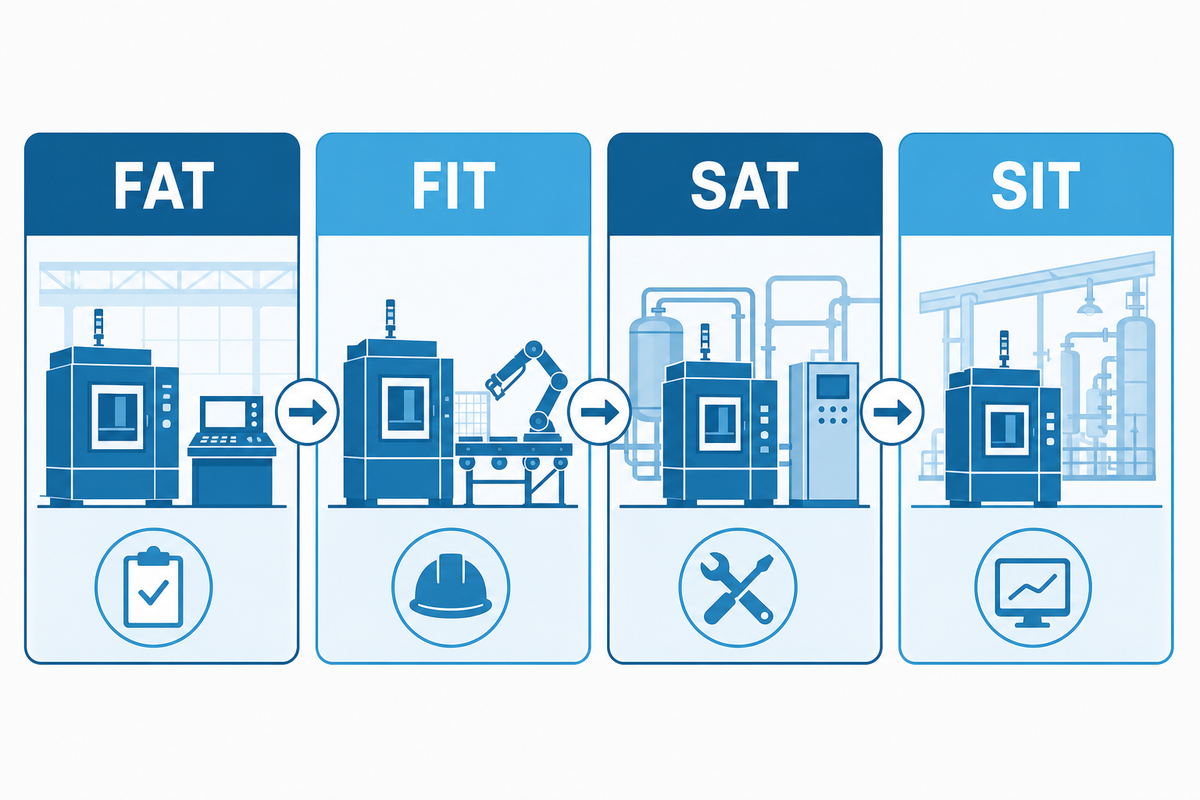
They often shorten these acceptance stages to “the machine passed FAT.” This leaves integration and product evidence unclear. Define each stage in the contract and test plan so they remain separate.
| Stage | Main question | Useful evidence |
|---|---|---|
| FAT, Factory Acceptance Test | Does the machine execute the agreed functions repeatably at the supplier site? | Recipe control, motion, dispense checks, alarms, guards, cleaning, changeover, restart, sample runs, calibration status and data export |
| FIT, Factory Integration Test | Does it communicate and physically integrate with the line? | Electrical/mechanical interfaces, utility load, handshakes, line timing, reject handling, upstream/downstream stops |
| SAT, Site Acceptance Test | Does the installed equipment operate under site conditions? | Actual utilities, environment, operator workflow, approved materials, installation checks, stop/restart and site safety functions |
| SIT, Site Integration/Test evidence | Does the installed process produce acceptable cartridges in the intended line? | Actual cartridge configuration, approved adhesive, process records, bond evidence, finished-filter test and traceable release record |
Form an agreement on sample, duration of test, material lots, permitted interventions, measurement system, reject definition, and disposition rules prior to starting the test. If an operator can stop the line and adjust a setting, discard several parts and restart the line without this recording, it means the test didn’t show stable good output. It means that acceptable samples can eventually be made.
Quality definition: defect categories, sampling, bond evidence, finished-filter test, raw-data retention, retest rules, and lot disposition. Record total cycles, accepted parts, rejected parts, planned and unplanned stops, adhesive waste, changeover time, and the test recipe. Keep the stages separate in the contract and test plan. The important metric is stable good output for the agreed upon cartridge.
Prepare a Requirement-First Supplier Worksheet
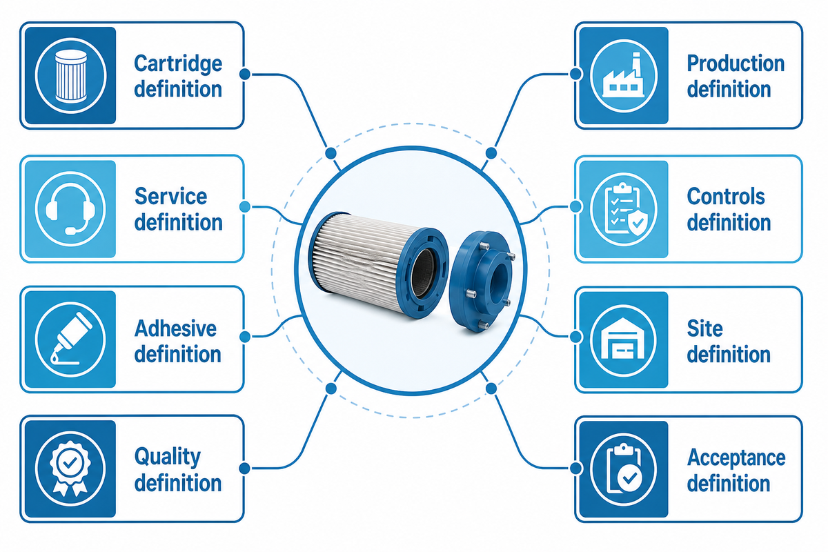
A requirement-first worksheet eliminates time spent on the unknowns during the supplier conversation. It is not a quotation form and does not duplicate the commercial solution page.
- Cartridge definition: Drawings, tolerances, end-cap material, media, core/cage, contact area, engagement depth, allowable squeeze-out, and variant range.
- Service definition: fluid, temperature, pressure, vibration, cleaning or sterilization, storage, and cleanliness constraints.
- Adhesive definition: grade and revision, TDS/SDS, A/B ratio where applicable, storage and conditioning, viscosity range, cure basis (open/work/fixture/full), and approved surface preparation.
- Quality definition: defect categories, sampling, bond evidence, finished-filter tests, retention of raw data, retest rules, and lot disposition.
- Production definition: accepted-output target, allowed intervention, changeover range, cleaning/purge plan, mixer/nozzle consumption, planned downtime, and waste handling.
- Controls definition: recipe permissions, operator roles, alarms, audit trail, data export, material-lot linkage, calibration, and backup/recovery.
- Site definition: power, compressed air, ventilation, extraction, temperature/humidity, floor/load/space, line interfaces, guarding, and safe chemical handling.
- Acceptance definition: FAT, FIT, SAT, and SIT scope with samples, instruments, methods, limits, responsibilities, and deliverables.
Send representative parts and realistic process materials early enough for trials. Substitute production materials when you can’t release the production material and document the gap. A demonstration using an easy-to-use adhesive with an idealized cap or a non-functioning prototype can show the motion; however, this doesn’t address process qualification.
Include process safety in the requirement pack as well as product quality. The selected adhesive and curing method may require ventilation, guarded hot surfaces, spill control, personal protective equipment, and procedures for purging, maintenance, or an abnormal mixing reaction. Base those controls on the current safety data sheets, supplier instructions, and the site’s risk assessment rather than copying a generic machine checklist.
Ready to translate the worksheet into a machine configuration?
Review the commercial solution page, then share your cartridge drawings, materials, adhesive information, acceptance method, and integration requirements with UDMachine.
Frequently Asked Questions
What does a filter cartridge end cap gluing machine do?
It meters and places adhesive in or on the end cap, controls the dispensing path and cycle, and may manage two-part proportioning, mixing, heating, cap positioning, alarms, and recipe data. Its purpose is to make filter end cap gluing repeatable across a defined production run. The machine can also preserve the settings and checks that explain how a part was made. The final cartridge still needs an approved bond check and a filter-level test appropriate to its application, because stable dispensing doesn’t prove every unmonitored interface or finished-filter outcome.
Which adhesive is best for filter cartridge end caps?
There’s no universal best adhesive. The choice depends on cap and media materials, joint gap, service fluid, temperature, cleaning chemicals, pressure, vibration, cleanliness requirements, and the line’s allowable open and cure time. Compare two-component polyurethane, epoxy, conventional hot melt, and reactive hot melt against those inputs, then test the selected grade on actual parts under the intended process.
Is gluing better than ultrasonic welding?
Gluing is often more flexible for dissimilar materials, composites, thermosets, heat-sensitive parts, or gaps that need filling. Welding can be cleaner and faster for compatible thermoplastics because it removes adhesive and cure management. The better route depends on resin compatibility, joint design, media sensitivity, tooling, flash control, cleanliness, and required validation. Treat it as a cartridge-configuration decision, not a general rule.
How do you verify that an end-cap bond is good?
Begin with traceable materials and an approved process window. Confirm the recorded ratio or dispense checks, inspect the joint using an approved method, and use representative sectioning, coupons, hardness, or mechanical evidence when the risk justifies it. Then run the specified finished-filter integrity or pressure test under defined conditions. No single visual check or PLC green light proves every performance requirement.
What should be tested during FAT?
FAT should show that the machine executes the agreed recipe repeatedly, measures the required variables, triggers alarms, handles stops and restarts, supports cleaning and changeover, and preserves useful records. Run representative materials and parts where practical. Define sample size, acceptance limits, reject rules, interventions, and test instruments before FAT so a short demonstration isn’t mistaken for process qualification.
Can the machine’s PLC data prove filter performance?
No. PLC data can show that monitored machine variables stayed inside programmed limits. It can’t by itself prove particle or microbial retention, leak tightness, pressure life, or field durability. Those claims require a validated relationship between the bonding process and an appropriate finished-filter test, with the method, conditions, instrument, raw result, and acceptance limit recorded.
What causes bubbles or voids in an end-cap bond?
Common causes include air introduced during material refill or mixing, unstable feed, incomplete purge, a broken bead path, poor filling geometry, cure shrinkage, or moving the cap before the joint has set. Diagnose from material lots, ratio or dispense checks, pressure and temperature trends, bead observations, and destructive sections. Don’t solve every void by increasing volume; excess material can create overflow.
What information should be sent to a machine supplier?
Send cartridge drawings and tolerances, cap/media/core materials, service conditions, adhesive TDS/SDS if selected, output definition, good-part test, acceptable defect criteria, changeover range, cleaning method, traceability needs, utilities, and safety constraints. If the adhesive isn’t fixed, state the alternatives and required qualification work. This lets the supplier configure and test the actual process instead of quoting from diameter alone.
About UDMachine
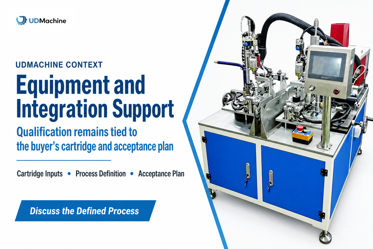
Suzhou UDTECH Technology Co., Ltd., operating as UDMachine, designs and supplies filter-cartridge production equipment and line-integration support. Company background is presented separately from product validation: the suitability of any end-cap joining process must still be confirmed against the buyer’s cartridge, adhesive, service conditions, and acceptance plan.
References & Sources
- 3M, Choosing and Using a Structural Adhesive.
- 3M, Surface Preparation and Pretreatment for Structural Adhesives.
- NASA, Process Specification for Adhesive Bonding (used as a process-evidence model, not a filter-cartridge acceptance standard).
- Peer-reviewed study, Defect Detection Sensitivity of Bubble-Point-Type Tests for Sterilizing-Grade Membrane Cartridge Filters.
- Dukane, Guide to Ultrasonic Plastics Assembly.
- Filtration + Separation, Understanding Adhesives for Filter Fabrication.
UDTECH / ENGINEERING GUIDE
About UDMachine
UDTECH publishes practical production-line planning guides for filter cartridge making, assembly, finishing, and complete-line projects.
Use these guides to define cartridge type, process route, target output, available utilities, acceptance evidence, delivery scope, and installation constraints before selecting equipment.
Start with the cartridge
Media, diameter, length, end-cap format, and rated output define the real machine route.
Clarify the line scope
Utilities, layout, automation level, inspection points, and acceptance tests vary by project.
PRODUCT / CAPACITY / ACCEPTANCE
Prepare Your Line Brief
Product types
PP Melt Blown · String Wound · CTO Carbon · UDF Tube
Start with
Cartridge type · Target output · Country
Planning inputs
Utilities · Layout · Process · Acceptance standard
Response route
Submit the website inquiry form
Submit Project Brief