Get in touch with Suzhou UDTECH Technology Co., Ltd. Company

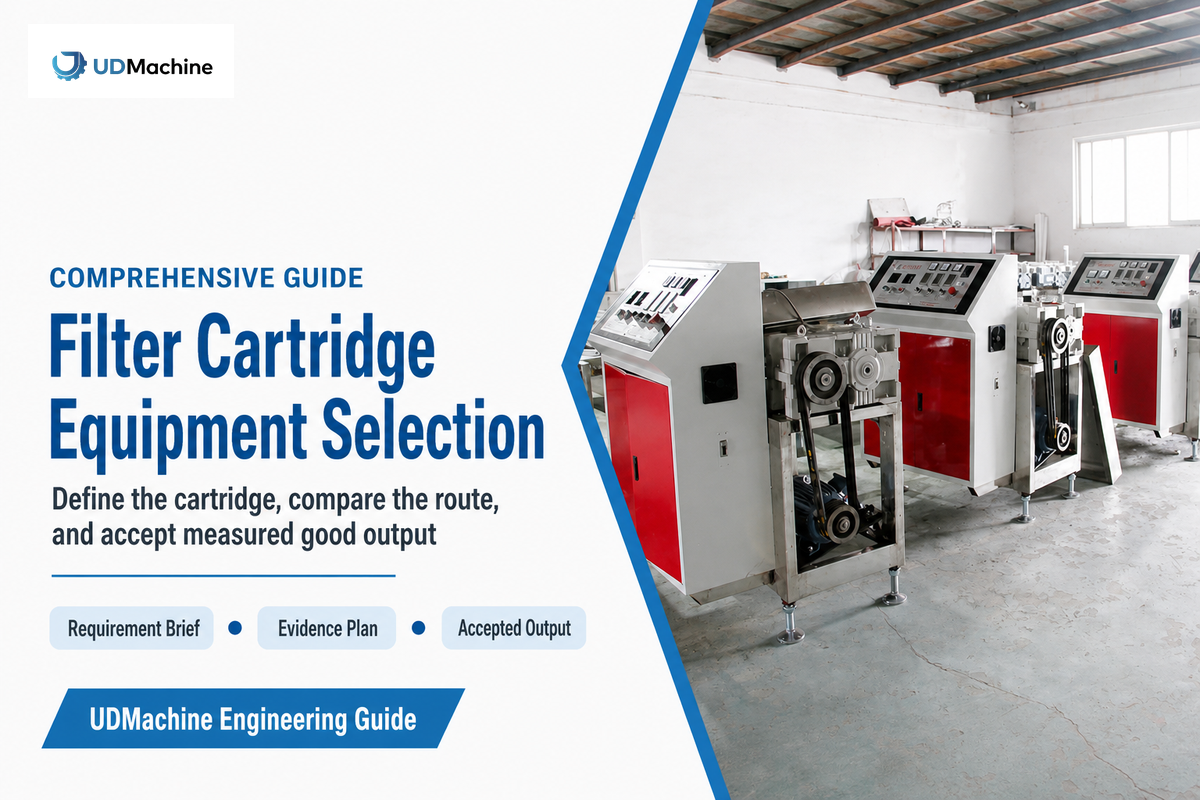
Filter cartridge production guide · Updated September 2026
Turn a finished-cartridge requirement into a comparable equipment brief, proof plan, factory acceptance test, and defensible investment decision.
Filter Cartridge Equipment Selection is the process of matching a defined cartridge, application, production route, proof plan, site boundary, and accepted-output target to the equipment purchase, not simply choosing the fastest machine in a brochure. Define the product, separate product proof from process proof, align every quotation to the same scope, and accept the line against measured good output.
The production line may produce the required shape, but that may not provide the customer with evidence that the cartridge meets its requirements. The opposite may be the case as well: a sample may pass a limited scope test, while the proposed process lacks the necessary controls to replicate that effect. Therefore, a sound procurement decision includes both evidence trails: the acceptance of finished-cartridge and the capability of the machine/process.
This manual has a different function than UDMachine’s filter cartridge equipment selection solution page. The solution page has a commercial configuration and published specifications for a route-specific design and customer request. This manual has a different focus: how to prepare a brief, assess dissimilar quotes, plan proof, FAT and SAT, and measure the cost of each accepted cartridge. Separating these functions helps avoid confusion and an unnecessary sales page for the same request.
Scope note: Water, hydraulic, ventilation, food, pharmaceutical, chemical-process, and other cartridges do not use interchangeable test meanings. The examples below are procurement aids, not a universal product standard, safety certification, or substitute for applicable local rules, the equipment manual, and a qualified engineering review.
1 · Define
Application, cartridge, contaminant, rating basis, and good output
Application, cartridge, contaminant, rating basis, and good output
2 · Translate
Route, materials, geometry, utilities, interfaces, and controls
Route, materials, geometry, utilities, interfaces, and controls
3 · Prove
Samples, measurements, process evidence, FAT, and site checks
Samples, measurements, process evidence, FAT, and site checks
4 · Decide
Accepted output, open risks, owners, next tests, and commercial fit
Accepted output, open risks, owners, next tests, and commercial fit
1. What Filter Cartridge Equipment Selection Actually Covers
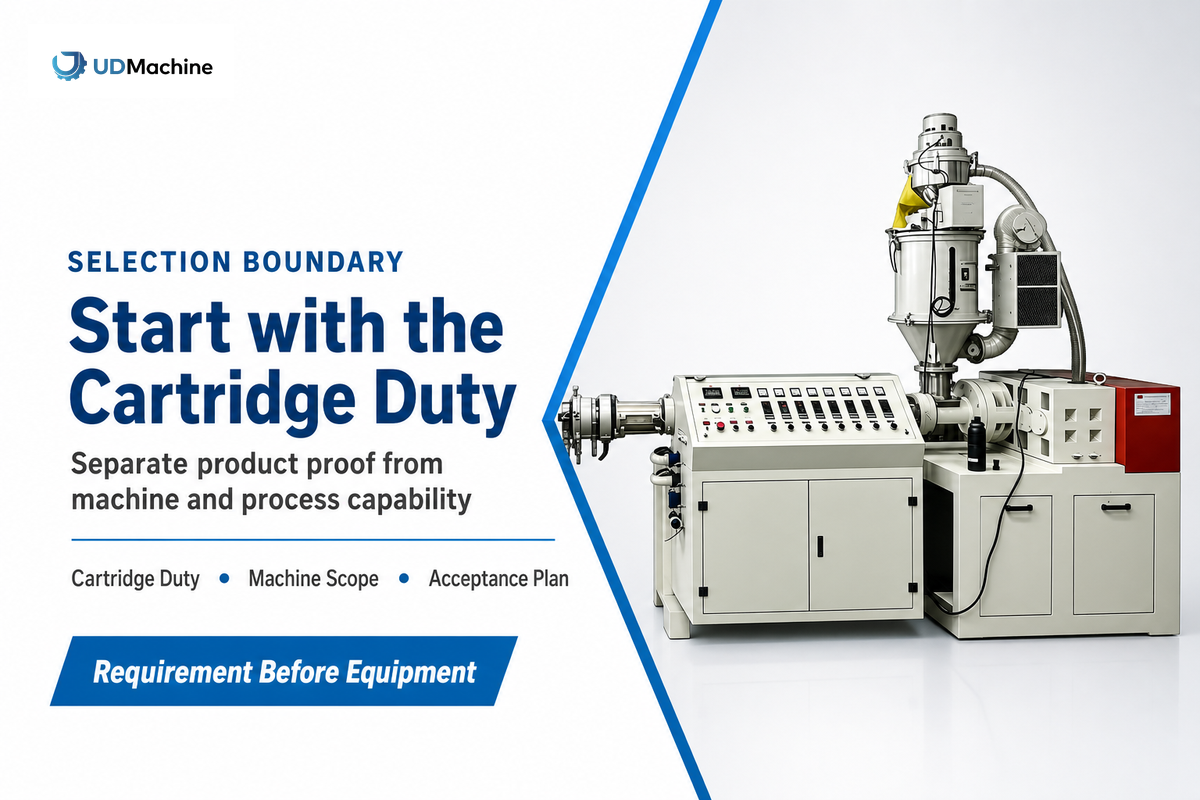
The selection of equipment is the controlled conversion of a requirement for a finished cartridge into a manufacturing route, the scope of the machines, the evidence plan, and the acceptance decision. This is unlike the procurement of a replacement cartridge for a filter housing in operation. This is also broader than choosing a winder, extruder, or thermal bonding machine from a catalog.
The beginning is defining the application. Cartridges made for process water, hydraulic circuits, dust collection, food-contact service, or pharmaceutical processing may share a cylindrical shape but have different failure meanings. Two equipment proposals can only be compared after the fluid or air stream, contaminant, material compatibility, pressure or temperature exposure, rating language, and test method have been specified.
The general logic of the University of Georgia’s filtration guidance shows the following in relation to a cartridge: media, suspended-pore size, particle size, loading, and required flow. The page is on household water treatment, thus it isn’t providing a rule for an industrial machine. However, it does show that one micron label can’t define a manufacturing project.
| Decision | Question | Primary evidence | Typical owner |
|---|---|---|---|
| Cartridge duty | What must the finished element do? | Approved product specification and test basis | Product engineering / QA |
| Manufacturing route | Which process can create the required structure? | Route description, sample history, control plan | Process engineering |
| Machine scope | What is included from raw material to accepted output? | Scope matrix, interfaces, utility list, drawings | Plant engineering |
| Commercial decision | Which offer meets the requirement at acceptable risk? | Normalized quotation, acceptance plan, lifecycle assumptions | Procurement / finance |
Decision rule: Never let one document answer a question it was not built to answer. Machine nameplates aren’t finished-filter tests. Sample reports don’t prove repeatable production. General certificates aren’t application-specific acceptance methods.
Vocabulary bridge between filter use and filter production
Search results often mix finished-filter selection with manufacturing-equipment procurement. In a liquid filtration or water filtration system, cartridge filters are used to retain sediment, impurity, or another defined contaminant, before the fluid reaches downstream equipment or a controlled effluent point. These end-use conditions are important to the factory, since they define the cartridge, but don’t select the production machine by themselves. Use the route-to-proof table as a filter cartridge equipment selection chart, not as a universal rating table. A filter cartridge equipment selection calculator can normalize commercial inputs, but it can’t determine cartridge filter micron size without a named test basis.
Finished-filter language: translate it before equipment selection
Finished-filter searches may use filtration equipment, water filter cartridge, industrial cartridge filter, types of industrial cartridge filters, types of cartridge filters, string wound filter cartridges, wound cartridge, cylindrical filter, industrial filters, or the type of cartridge. These are useful starting labels, not a machine specification. The selection process must first identify the correct filter, proper filter, or right cartridge filter for the service, then translate that filter type into a material stack, geometry, joining method, output basis, and proof plan. A product being easy to replace or available in various micron ratings says little about how it must be made.
Application language is another input. A filter system or filtration process may need to remove suspended solids, protect downstream equipment, support water treatment applications, or handle gas filtration. Some products are commonly used in water treatment; others require more frequent cleaning or replacement. Those facts influence the level of filtration, filter efficiency, filtration standards, and type of filtration, but they do not choose the line. The cartridge needed depends on fluid, contaminant, temperature, pressure, compatibility, and acceptance method.
When engineers and operators select the right filter, key factors to consider include the type of filter media, required efficiency, service conditions, and changeout plan. A pleated design may provide a higher filtration area, which makes them ideal for applications where space is limited, but that still does not select the right manufacturing route. These key factors do not make cartridge solutions interchangeable. A supplier page covering types of media may help discovery; equipment decisions still need testable boundaries. To select the right machine for optimal performance and cost-effectiveness, freeze the product and proof brief before comparing offers.
Cartridge filters may use depth, pleated, membrane, adsorptive, or other designs. The cartridge type determines the route, while the filter media affects pore structure, surface area, filtration area, compatibility, and joining. A depth-filtration cartridge may construct its structure using melt-blown fibers or a wound pattern; an SOE cartridge describes a single-open-end connection that also affects the drawing, end treatment, and compatible cartridge filter housings.
Flow terms require the same level of detail as other terms. High-flow claims should state the fluid, temperature, pressure drop, housing, and number of elements. Higher flow rates may change the product test even when the machine is unchanged. Report the design flow rate (often shown as GPM in US water systems) and the maximum flow rate permitted by the approved test basis. “higher flow” and “maximum flow” can’t be independent acceptance criteria.
For food and beverage, hydraulic, ventilation, and other industrial processes, specify the right cartridge before selecting the route. Ask which particles are anticipated to pass through the filter, which particles must be retained, and how that result is to be determined. The objective isn’t a generic claim of optimal performance; it’s a repeatable product result within the named application and operating boundary.
2. Start with a Cartridge Brief, Not a Machine Brochure
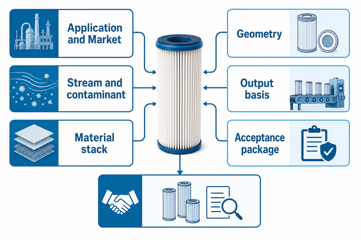
A supplier quoting a task can’t be compared with another supplier quoting the same task when each is making different assumptions. The compact cartridge brief should be frozen before the quoting process. “Ten-inch water filter, five micron, high output” isn’t a brief; it leaves the rating basis, media, geometry, output basis, acceptance test, and line scope undetermined.
Buyer Asset: 10-Field Cartridge Brief
- Define Application and Market: water, hydraulic, ventilation, food, pharmaceutical, chemical process or another specific application; destination country and approval basis.
- Describe Stream and contaminant: fluid or air, viscosity as applicable, particle or adsorbate description, loading pattern, temperature, and exposure to chemicals.
- Name the cartridge family: PP melt-blown, string wound, pleated, CTO activated carbon, support tube or another defined construction.
- List the Material stack: media, core, end caps, adhesive or thermal joint, gasket or O-ring, and restrictions on additives or contact materials.
- Set Geometry: OD, ID, length, end configuration, seal position, core details, tolerances, and the drawing revision that governs.
- Define Performance language: micron or adsorption target, nominal/absolute wording if used, differential-pressure boundary, and the test method that gives those words meaning.
- Specify Structural and compatibility checks: temperature exposure, fluid compatibility, integrity, collapse/burst, dimensional stability, seal checks as needed.
- Set the Output basis: accepted cartridges per hour or shift, scheduled time, product mix, changeovers, inspection sampling, and planned uptime.
- Record Site inputs: voltage/frequency, power limit, compressed air, water, extraction, floor area, height, access, network/PLC protocol, and downstream rate.
- Agree the Acceptance package: sample quantity, measurements, pass/fail limits, FAT recipe, site checks, documents, training, spares, and sign-off owner.
Normalize units in the brief: record OD, ID, length, runout, and clearance in mm; liquid flow in L/min or GPM; air or fluid pressure in kPa, bar, or PSI; temperature in °C; connected and observed electrical demand in kW; compressed-air demand in L/min or Nm³/h; cycle and changeover time in s, min, or h; and acceptance, scrap, and uptime as %. These are reporting fields, not suggested limits.
A good brief contains blanks. A blank marked “owner: QA; due before FAT” is safer than a guessed value copied from a supplier. It exposes what must be resolved and stops silent assumptions from becoming purchase-order obligations.
Send the same revision to every bidder. Require a compliance response beside each row: meets as written, meets with stated condition, deviation, or open pending test. This simple discipline makes quotation differences visible before the project reaches layout approval.
Example: turn a vague request into a testable brief
In the example “a line for 10-inch PP cartridges, 5 micron, 1,000 pieces per hour,” procurement may feel it has defined the product, size, rating, and output. However, the process team still can’t determine whether the cartridge is coreless or cored, whether the length is nominal or tolerance-controlled, which resin is approved, how the density profile is defined, what “5 micron” means, how many product variants will be made, or whether cutting and packaging are included in the quoted rate.
The request should include the application and test basis; OD, ID, finished length and tolerances; resin and additive “rules;” core and end configuration; density or weight fields; rating language; sample plan; accepted pieces per hour after the defined inspection; electrical and air supply; included cutting/handling; and the FAT run duration. The supplier can then state which values are proven, which require a trial, and which fall outside its scope. The project hasn’t become more complicated. The previously hidden decisions have become visible.
This visibility also prevents premature price negotiation. If Bid A includes automated cutting, extraction, measurement fixtures, training and commissioning, and Bid B stops at continuously forming a cartridge, their totals describe different assets, so scope comes first and price comes second.
3. Match Cartridge Type to the Manufacturing Route

The cartridge family determines the process route because each route creates structure in a different way. UDMachine publicly offers PP melt-blown, string-wound, and CTO activated-carbon equipment families. These are separate production routes; they aren’t different modes on a single universal machine.
| Cartridge type / route | Structure-forming step | Inputs to freeze | Process evidence to request | Finished-product evidence |
|---|---|---|---|---|
| PP melt-blown | Polymer melting, extrusion, fiber formation, collection, cooling, cutting | Resin grade, OD/ID/length, density profile, core option, surface finish | Temperature/pressure controls, fiber/weight consistency, line-state records, changeover sequence | Dimensions, mass/density, integrity, application-specific filtration test |
| String-wound | Controlled yarn winding around a core | Yarn, core, winding pattern, tension, length, end finish, product mix | Tension control, traverse recipe, layer repeatability, cut/end method, changeover time | Dimensions, winding integrity, mass, fit, application-specific filtration test |
| CTO carbon block | Powder preparation and extrusion/forming, followed by cooling and finishing | Carbon/binder system, particle form, dimensions, bore, adsorption duty, dust properties | Mix/feed consistency, forming conditions, dust-control interface, cut/finish sequence | Dimensions, structure, pressure drop, adsorption and application-specific tests |
| Pleated | Media converting, pleating, assembly, end joining and sealing | Media, pleat geometry, support layers, core/cage, end caps, seam, seal | Pleat control, joining recipe, adhesive/thermal conditions, fixture and cure records | Geometry, integrity, compatibility, structural and filtration tests for the duty |
| Support tube | Polymer extrusion or another specified tube-forming route | Resin, slot/perforation form, wall, OD/ID, length and straightness | Tooling, dimensional controls, cooling and cut records | Dimensions, open area, strength and assembly fit |
| Resin-bonded depth | Fiber/resin preparation, forming and thermal cure | Fiber, binder, cure window, density, core and dimensions | Mix/form/cure controls and batch traceability | Integrity, compatibility, dimensions and duty-specific filtration test |
| Membrane assembly | Membrane converting, pleating/wrapping, assembly and sealing | Membrane lot, support layers, seam, housing parts and sterilization boundary | Handling, joining, integrity-control and traceability records | Integrity plus application-specific retention and compatibility evidence |
| Metal or sintered | Powder/fiber forming, sintering and finishing | Alloy, particle/fiber basis, geometry, thermal cycle and finish | Furnace/atmosphere records, tooling, machining and cleaning scope | Porosity, strength, cleanliness, compatibility and duty test |
| Specialty hybrid | Two or more converting, forming, filling or joining routes | Layer order, material interfaces, intermediate storage and final assembly | Interface ownership, intermediate acceptance and change control | Layer, joint, structural and application-specific performance evidence |
What are the different types of filter cartridges?
A useful distinction separates common element families: melt-blown and string-wound depth elements, surface or pleated cartridges, activated-carbon blocks, membrane cartridges, and structural support tubes used within a larger assembly. The distinction isn’t simply a name. Ask how the structure is formed, which interfaces are created, which dimensional features control housing fit, and which final-product tests apply to the anticipated service. Two cartridges with the same outer size or micron label may still require different equipment, joining steps, controls, and proof.
Geometry shouldn’t be added as an afterthought. The 2024 patent application describing multiple arrangements of tube-shaped filter elements is a reminder that the structure of a design can depend on the geometry of the elements. A patent doesn’t mean a design will perform better or that a product will sell; it only means the arrangement and manufacturing form have been documented.
For each route, create a material-interface list: media-to-core, media-to-end-cap, seal-to-housing, adhesive-to-fluid, or carbon/binder-to-process stream. Record temperature and chemical exposure separately from dimensional fit. In hydraulic applications, for example, ISO 2943:1998 describes a scoped compatibility method that checks whether an element retains collapse/burst rating after exposure to a designated fluid at high or low temperature, and explicitly excludes the mounting seal. That is a valuable boundary lesson, not a test mandate for every cartridge.
4. Translate Micron and Particle Targets into Machine Requirements
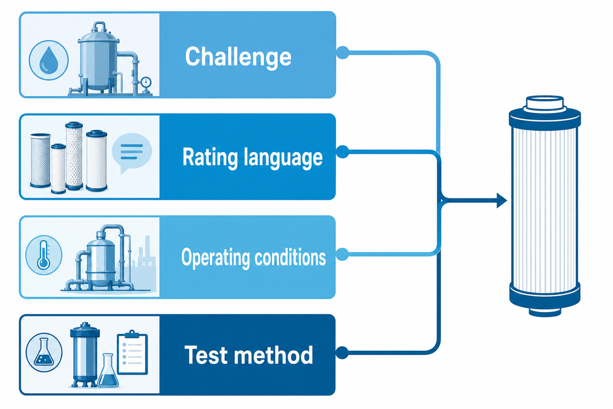
Micron targets belong in the finished-cartridge specification. This is not proof just because it is mentioned on the nameplate of a machine. Four things have to be established to use this target in an RFQ: the challenge, the language of the rating, the operating conditions, and the test method by which the determination of passing or failing is made.
| Phrase in a request | What remains unknown | Better RFQ entry |
|---|---|---|
| “5 micron cartridge” | Nominal/absolute meaning, challenge particle, efficiency, flow, pressure, fluid | Named rating basis and test method at stated conditions |
| “High dirt holding” | Contaminant, terminal pressure drop, feed concentration, test duration | Challenge and termination rule with report fields |
| “Low pressure drop” | Flow, viscosity, temperature, clean/loaded state, housing contribution | Allowed differential pressure at named test conditions |
| “Bubble-point passed” | Method, fluid, surface tension, integrity limit, performance meaning | Integrity acceptance rule plus separate filtration-performance test |
ISO 2942:2018 gives a precise example of why test names need scope. The abstract states that the first bubble point can verify fabrication integrity and identify the largest pore in a hydraulic-fluid-power filter element. It states that the first bubble point is not a functional characteristic, and cannot establish the filtration rating, efficiency, or retention capacity. Do not promote one integrity result into a broader product claim.
The same is true for pleat count and area. A 2026 Scientific Reports study showed that in its pleated-filter setup, pleat ratio, particle size, face velocity, and dust loading interacted with channel blockage and pressure drop along with the evaluated properties of the system. There’s no guarantee that a larger apparent area results in a larger usable area. The procurement lesson is to require evidentiary support for the challenge of interest, not to adopt the conditions of the paper as a universal cartridge design.
Which is finer, 30 micron or 100 micron?
Thirty microns is the smaller stated particle size, so it is described as finer. This doesn’t mean that every 30-micron cartridge would perform better than every 100-micron cartridge in real systems. Media, nominal or absolute rating basis, efficiency, contaminant shape, loading, fluid properties, flow, pressure drop, and test method still matter. For equipment selection, use the micron value as one product requirement and require a defined acceptance test. It shouldn’t be the sole criterion used to determine the manufacturing route.
5. Compare Flow, Pressure, Utilities, Interfaces, and Safe Service
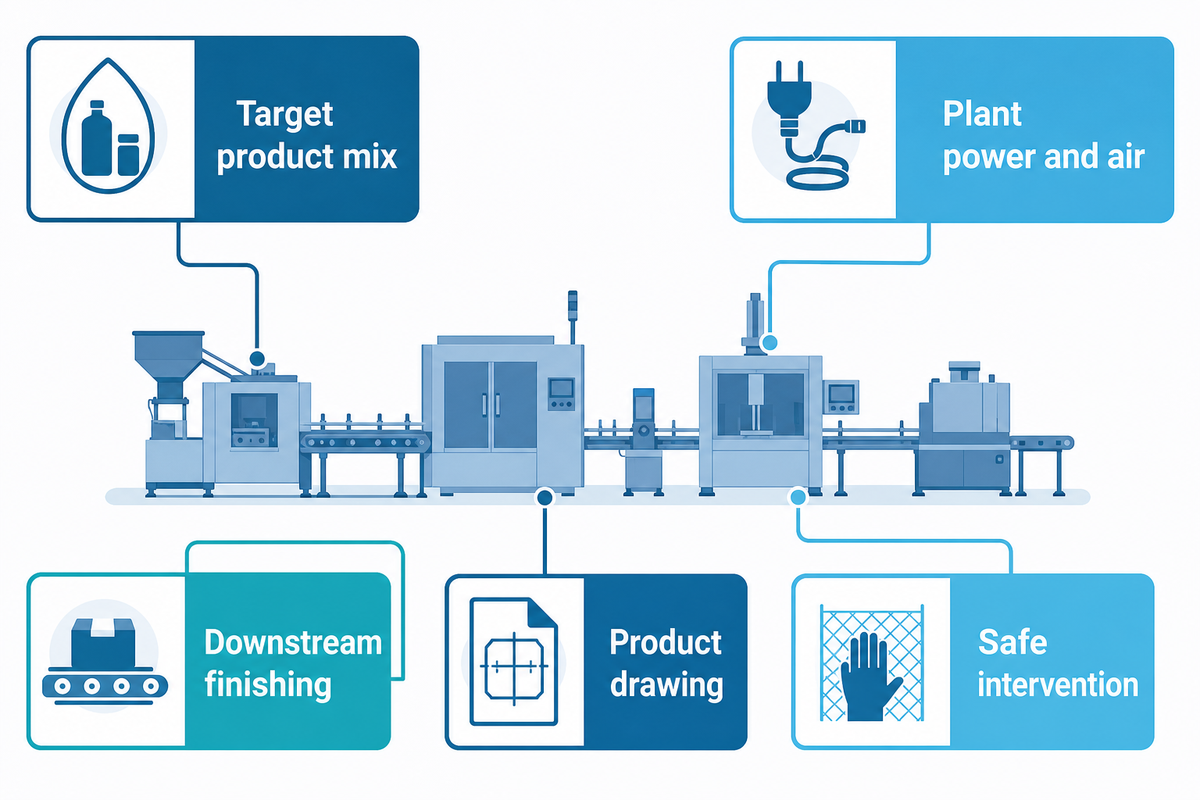
A forming machine that won’t fit in a plant is useless, no matter how capable it is. Utility demand, material handling, downstream finishing, product inspection, extraction, controls, access, and maintenance state must be looked at as one complete line installed.
The Five-Column Fit-to-Proof Map
| Requirement | Machine implication | Supplier evidence | Acceptance method | Owner |
|---|---|---|---|---|
| Target product mix | Tooling, recipe range, changeover sequence | Drawing set and changeover demonstration | Witness two defined products and record time/parts | Process engineer |
| Plant power and air | Connected load, peaks, pressure/quality needs | Load list and utility diagram | Measure under agreed production state | Facilities |
| Downstream finishing | Cutting, end finishing, assembly, packaging handoff | Scope and interface matrix | Run at matched rate without hidden WIP buildup | Production |
| Product drawing | OD/ID/length, core, ends, seal and tolerance tooling | Approved drawings and sample records | Sample plan and calibrated measurement | QA |
| Safe intervention | Isolation points, residual energy, access, restart logic | Energy map, procedure inputs, guard/interlock list | Witness stop, isolate, verify, restore sequence | EHS / maintenance |
It’s important not to merge connected loads with observed demand or to merge maximum machine cycles with released production. Provide the basis for every number: product, length, material, steady-state duration, operator count, inspection rate, and included auxiliaries. Without that basis, the comparison is merely a list of numbers.
Build an interface register before layout approval
The interface register assigns every handoff to the supplier, buyer, or a named third party. Start at raw-material receipt and continue to the accepted packaged cartridges. For each boundary, record the physical item, rate, height, orientation, buffer, signal, ownership, and acceptance method. Include polymer or yarn feeding, cores, powder handling, cutting, dust or fume extraction, cooling, end finishing, inspection, reject handling, packaging, data collection, and utilities.
There are numerous “by buyer” items to watch out for. A local chiller, compressor, dust collector, feeder, conveyor, printer, or test instrument may be reasonable, but its interface must be explicit. However, an implicit interface should be avoided. For those items, provide the required flow, pressure, temperature, cleanliness, electrical load, signal type, physical connection, fabrication and installation tolerances, and commissioning responsibility. If those inputs arrive after equipment fabrication, a small excluded item can trigger redesign, delay, or an acceptance dispute.
The same rule also applies to data and software. State whether the machine only controls its own process or must exchange recipe, order, count, alarm, quality, or traceability data with another system. Define the protocol, tag list, time stamps, user access, backup, change authorization, and who tests each signal. “PLC included” is not a sufficient answer.
Plan the service state with the same care as normal operation. In the United States, OSHA 1910.147 applies to servicing and maintenance where unexpected energization, start-up, or release of stored energy could injure employees. It includes cleaning and unjamming work when exposure exists. Ask where electrical, pneumatic, hydraulic, thermal, gravitational, or residual-pressure energy is isolated and how zero-energy verification is performed.
6. Use the 6-Stage Evidence Ladder to Compare Suppliers
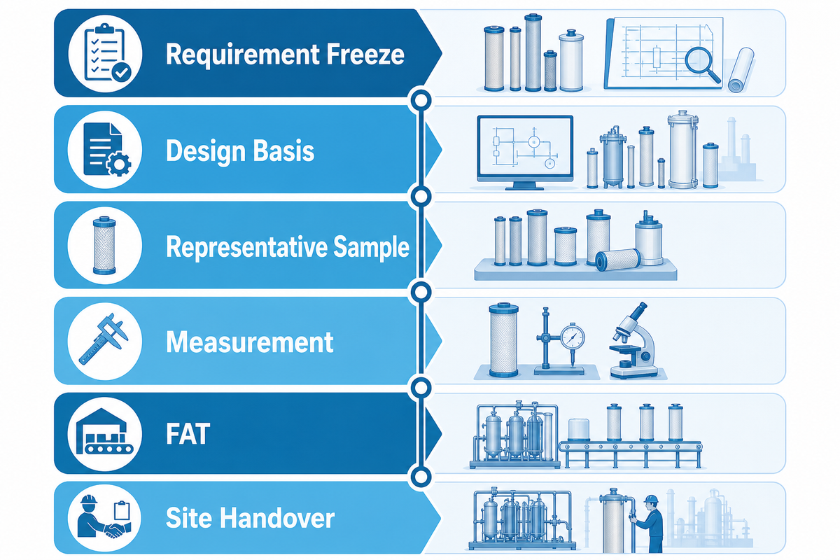
The Evidence Ladder prevents a polished brochure from being considered final proof. Each stage addresses a narrower question and each step generates a record that the subsequent stage may use. The supplier doesn’t “pass” the entire project at Stage 2; the risk only decreases as evidence is provided.
Stage 1 · Requirement Freeze
Approved application, drawing, material stack, performance language, output basis, site conditions, standards and owners.
Approved application, drawing, material stack, performance language, output basis, site conditions, standards and owners.
Stage 2 · Design Basis
Route, equipment scope, tooling, controls, utilities, interfaces, exclusions, assumptions and deviations tied to Stage 1.
Route, equipment scope, tooling, controls, utilities, interfaces, exclusions, assumptions and deviations tied to Stage 1.
Stage 3 · Representative Sample
Material batch, product revision, machine state, recipe, operator, timestamp and traceable sample IDs.
Material batch, product revision, machine state, recipe, operator, timestamp and traceable sample IDs.
Stage 4 · Measurement
Calibrated instruments, named methods, sample plan, results, deviations, retest rules and clear pass/fail limits.
Calibrated instruments, named methods, sample plan, results, deviations, retest rules and clear pass/fail limits.
Stage 5 · FAT
Agreed products, duration, output basis, changeover, safety checks, documents, training and punch-list ownership.
Agreed products, duration, output basis, changeover, safety checks, documents, training and punch-list ownership.
Stage 6 · Site Handover
Installed utilities, interfaces, extraction, local materials, SAT checks, operating records, spares and acceptance sign-off.
Installed utilities, interfaces, extraction, local materials, SAT checks, operating records, spares and acceptance sign-off.
Each stage must have an evidence owner and a subsequent action. “Supplier to confirm” isn’t a closing response. It must be “supplier to submit load list and utility diagram by design review; plant engineer approves or logs deviation.” If the test method remains open at design review, name the owner and due date.
Product inspection and process evidence need to be considered holistically, rather than one being a universal substitute for the other. Some end outcomes can be verified on a finished cartridge, while others require evidence that the forming, joining, curing, winding, or handling process occurred within its defined acceptable process limits. The exact balance depends on the product and the applicable quality system.
Choose representative samples and challenge states
Running only the easiest product at FAT can confirm basic operation while leaving the investment risk untouched. Select the sample set from the real product matrix. The candidates could be the shortest and the longest length, the minimum and maximum OD, core and coreless combinations, the most difficult material, the finest density or winding sequence, the highest material volumetric flow rate, and the tooling or cleaning intensive changeover.
Not every extreme should be grouped into a single “worst case.” One condition can be the most difficult for dimensional control, while another may be the most difficult for joining, cooling, cutting, dust control or inspection. State the failure mechanism each challenge is meant to expose. This makes the required test set smaller and more informative. Long products may challenge straightness, heavier carbon mixes may challenge feed consistency, and smaller bores may challenge clearance.
Define repetition prior to the test. One good cartridge after many adjustments is a setup result, not stable output. Record warm-up, adjustments, stops, rejected pieces, rework, operator actions, material lot, and sample time. If a parameter changes after an early failure, decide whether previous results remain valid and which measurements must be repeated. The test report should document what transpired during the run and not only display the best results.
Evidence-language test: ask what the record proves and what it does not prove. “Dimensions passed on 20 samples” does not prove filtration efficiency. “Recipe temperature was in range” does not prove every joint is sound. “Bubble point passed” does not prove retention capacity. Clear limits make the package stronger, not weaker.
7. Compare Economics Using Accepted Good Cartridges
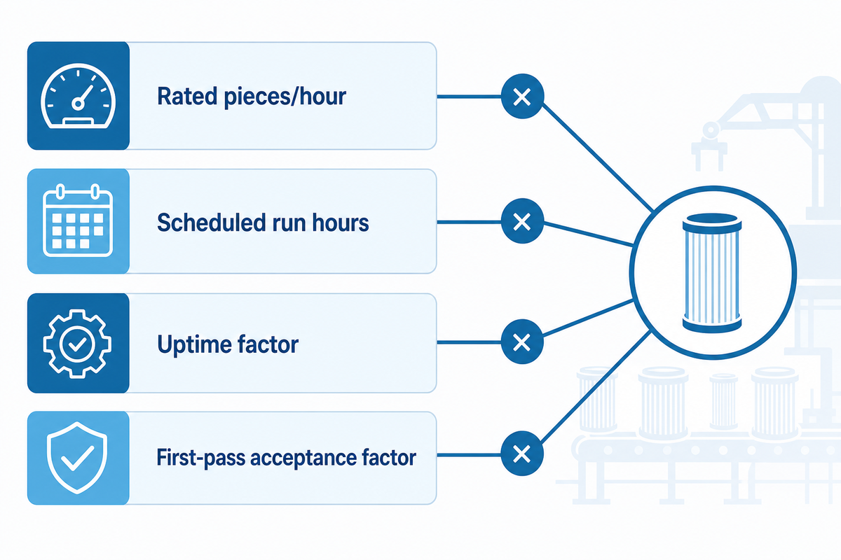
Rated speed is only one of many input factors. For procurement, there needs to be a common output denominator that includes planned operating time, uptime, first-pass acceptance rate, rework and scrap, changeover, labor, utilities and consumables, maintenance, and scope that’s included.
Good-Output Cost Worksheet
Accepted pieces per shift = rated pieces/hour × scheduled run hours × uptime factor × first-pass acceptance factor
Where:
rated pieces/hour = average pieces processed per hour during continuous operation.
Adjusted accepted pieces = accepted pieces + approved reworked pieces − downstream rejects attributable to the process
Cost per 1,000 accepted cartridges = shift cost ÷ adjusted accepted pieces × 1,000
Example
For shift cost, all bids must have a common boundary for the following elements: material, direct labor, utilities, consumables, planned maintenance, service allowance, quality checks, and the excluded steps of downstream/upstream.
Illustrative example only: Line A is quoted at 1,000 pieces/hour and Line B at 900. For an 8-hour scheduled shift, assume A has 80% uptime and 94% first-pass acceptance, while B has 90% uptime and 98% first-pass acceptance. Line A yields exactly 6,016 first-pass accepted pieces; Line B yields 6,350.4, or 6,350 whole pieces when fractional output is excluded. The nominally slower line produces more accepted pieces under these buyer-entered assumptions. This doesn’t predict either supplier’s performance. It shows why the assumptions must be tested and written into the comparison.
| Input | Line A example | Line B example | Evidence needed |
|---|---|---|---|
| Quoted rate | 1,000/h | 900/h | Product, material, length, operator and steady-state basis |
| Uptime assumption | 80% | 90% | Observed run duration and coded downtime |
| First-pass acceptance | 94% | 98% | Frozen test, sample plan and failure categories |
| Accepted pieces | 6,016 | 6,350 | Recalculate from witnessed evidence |
What should a filter cartridge equipment quote include?
A comparable quote should identify the exact product and material basis, included machines and auxiliaries, exclusions, tooling, expected output basis, utilities, controls, footprint, interface points, changeover scope, inspection equipment, documentation, FAT conditions, installation/commissioning scope, training, warranty, spare parts, and open assumptions. Ask the supplier to answer the same brief row by row. Lower prices may simply exclude cutting, end finishing, extraction, quality inspection, packaging handoff, or site commissioning that another supplier includes.
8. Screen Safety, Standards, and Factory Acceptance
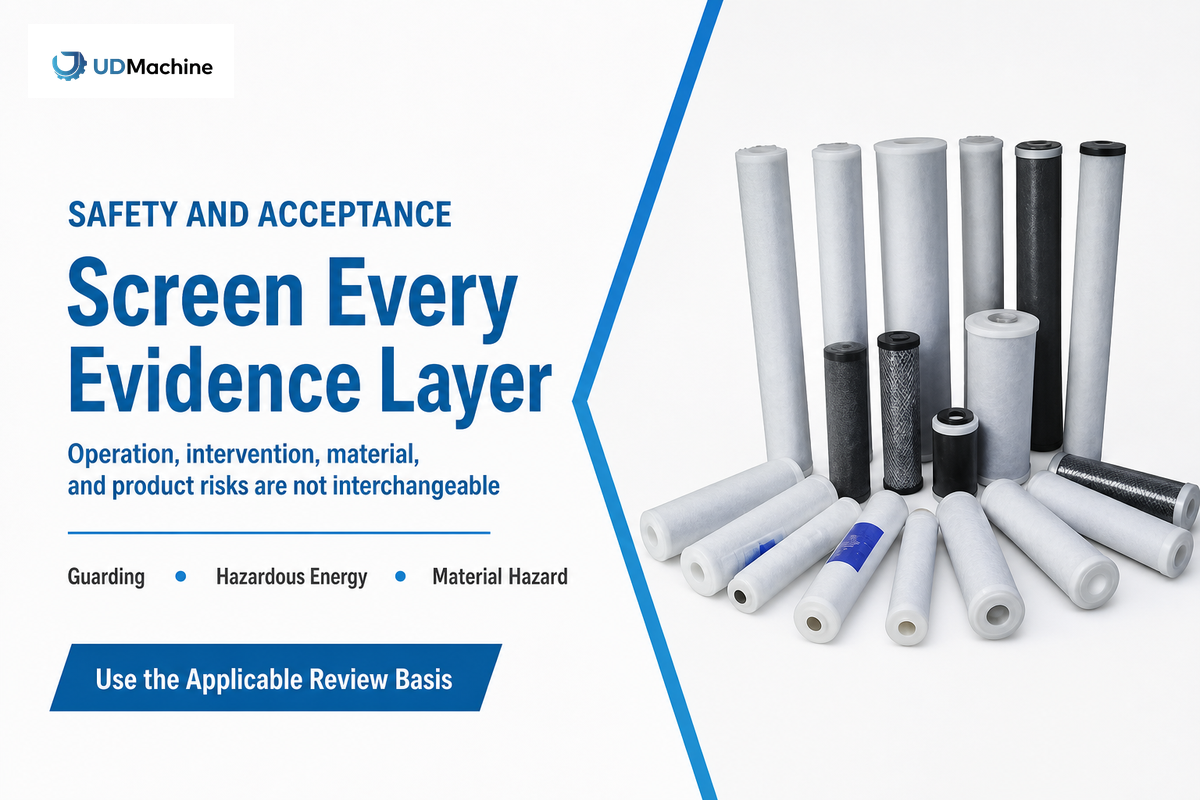
Safety evidence has at least three layers: hazards during normal operation, hazards during intervention or service, and hazards created by the processed material. Passing one layer doesn’t close the others.
For US workplaces, OSHA’s general machine-guarding rule says guarding methods must protect workers from hazards such as the point of operation, ingoing nip points, and rotating parts. Use that as a prompt to request a hazard list, guard layout, interlock functions, stop categories, restart behavior, and witnessed checks. It isn’t a certificate that any specific design is safe.
| Evidence family | Questions to close | FAT or design-review evidence | Scope caution |
|---|---|---|---|
| Operation guarding | Nip, cut, rotating, hot, moving and ejection hazards? | Guard/interlock list; stop and restart witness | Local law and risk assessment govern |
| Hazardous energy | Cleaning, unjamming, setup, blade/tool change, residual heat or pressure? | Energy map, isolation points, bleed/block method, verification inputs | Requires machine- and site-specific procedure |
| Material/process hazard | Dust, fumes, heat, polymer, solvent, additive or pressure hazard? | Material data, hazard review, extraction/collection interface, controls | Do not classify by route name alone |
| Product acceptance | Which samples, methods, limits and failure actions? | Approved FAT protocol and signed result pack | FAT conditions may differ from installed duty |
CTO and other particulate-handling routes need a conditional combustible-dust screen. OSHA explains that finely divided combustible material can become explosible when suspended in air at sufficient concentration and under particular conditions. The material, particle form, process, collection system, housekeeping, ignition sources, and facility determine the next review; “carbon line” alone doesn’t.
NFPA lists NFPA 660 as the 2025 Standard for Combustible Dusts and Particulate Solids and identifies it as a consolidation of earlier dust standards. The useful procurement action is to ask a qualified site team which provisions apply after the hazard screen, not to declare every CTO project subject to the same design by default.
Write FAT as a measurement contract
- Freeze product revisions: material batch, drawing, cartridge family, lengths, recipes and planned product mix.
- Freeze the operating window: warm-up, steady-state duration, operator roles, included auxiliaries and allowed adjustments.
- Define sample handling: sample count, IDs, timing, locations, conditioning, instrument and calibration status.
- Set pass/fail limits: dimensions, mass or density, workmanship, integrity, application-specific test, output, changeover and safety checks.
- Record deviations: who can approve a change, what triggers retest, and whether the change affects another result.
- Close the handover: punch-list owner, due date, document language, software backup, spare parts, training and SAT boundary.
Use the same frozen duty at SAT, then add installed-site variables: actual utilities, local raw materials, extraction, upstream/downstream handoffs, network integration, ambient conditions, maintenance access, and local acceptance roles. FAT proves the agreed factory test; SAT proves the installed boundary. Neither should silently replace the other.
9. Build a Decision Matrix and Know When to Ask for a Line Review
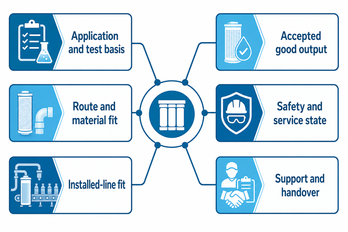
The final shortlist should make uncertainty visible. Weighted scores without evidence can reward the most confident brochure. Use pass, hold, retest, or reject beside every decision-critical item, then record the evidence, owner, and next date.
| Criterion | Minimum evidence | Pass | Hold / retest trigger | Owner |
|---|---|---|---|---|
| Application and test basis | Approved brief and method | Named and agreed | Generic “meets micron” claim only | QA |
| Route and material fit | Material stack, drawing, sample trace | All interfaces closed | Seal, joint, compatibility or structural gap | Product / process engineering |
| Installed-line fit | Layout, utilities, scope and interface matrix | Within site boundary | Excluded auxiliary or unmatched handoff | Plant engineering |
| Accepted good output | Witnessed rate, duration, acceptance and downtime | Meets frozen basis | Nameplate speed without accepted-piece evidence | Production / finance |
| Safety and service state | Hazard review, guards, isolation and material controls | Owners and actions closed | Unresolved intervention or dust condition | EHS / maintenance |
| Support and handover | Training, documents, backups, spares and response terms | Accepted package | Critical dependency without owner/date | Maintenance / procurement |
Score risk after proof, not before it
Weights become relevant after minimum gates are set. Product route, applicable acceptance method, site fit, and unresolved safety conditions should be pass-or-hold criteria rather than points that a low price can offset. Assuming all the bidders pass the minimum gates, the rest of the trade-offs will be scored and prioritized as follows: changeover burden, evidence quality, lifecycle cost, service response, spare parts plan, delivery, training, and commercial terms.
Record confidence for each score. Witnessed results may receive high confidence; drawing reviews may receive medium confidence; untested supplier statements may receive low confidence and a next action. This ensures that weak evidence doesn’t remain hidden behind a large and complicated spreadsheet. If two offers have similar totals but one rests on fewer open assumptions, the confidence column often explains the safer decision better than another decimal point in the weight.
Prior to the order placement, close the service and agree the handover terms. List critical wear parts, long-lead spares, consumables, special tools, software backups, remote-access conditions, response channel, training audience, document language, and the information required for preventive maintenance. Agree on who has ownership of the process recipes and the support available for a new cartridge material or dimension. The line will be asked to make more than the FAT sample; change governance is part of the investment.
Request an engineering line review when the cartridge route is clear but other boundaries remain open: several lengths or materials, an unproven seal/end configuration, unknown dust behavior, restricted utilities, an existing downstream machine, local certification, a demanding changeover target, or a product test that can’t be run at the supplier’s factory.
In this case, take the frozen brief to the commercial equipment-selection page and look at the most appropriate route without defining its details here. Research UDMachine’s company profile to learn more about the supplier. Information provided on the company page must be regarded as supplied by the company and must be verified during supplier qualification.
Have a cartridge brief but still have open assumptions?
Submit the application, cartridge drawing, material stack, target good-output rate, site utilities, acceptance basis, and any existing upstream or downstream equipment so the review can identify the likely route, missing interfaces, trial requirements, and scope boundaries before quotations are compared.
Frequently Asked Questions
How do you choose the right filter cartridge?
Start with the application, fluid or air stream, contaminant, loading, flow, pressure/temperature boundary, material compatibility, housing geometry, rating language, and applicable test method. Select the cartridge family after these inputs are clear. For manufacturing equipment, add the material stack along with the drawing, output basis, route, quality checks, utilities, and acceptance evidence. Although deciding on the cartridge and the correct machine are related decisions, they aren’t the same.
What types of equipment are needed for filter cartridge production?
A PP melt-blown route can include polymer feeding, extrusion or fiber formation, collection, cooling, and cutting. String-wound routes are centered around core handling, controlled winding and cutting. The CTO route involves powder preparation, mixing or feeding, forming or extrusion, cooling, and finishing. Pleated products add media converting, pleating, assembly, and joining. Inspection, dust extraction, material handling, packaging and utilities may be included or excluded, so full scopes should be compared rather than machine names.
What is the difference between nominal and absolute micron ratings?
Many systems have rating conventions, but their meaning varies depending on the stated method and the manufacturer’s definition. Nominal ratings often describe partial removal under defined conditions; absolute ratings are generally tied to a stronger removal threshold, but neither term is useful without a test basis, efficiency statement, challenge particle, flow, pressure, and fluid. Don’t assume two suppliers will use the terms in the same way. Specify the method and pass/fail criterion in the product specification.
How often should a cartridge filter be cleaned or replaced?
There is no universal replacement interval. Use the approved operating rule in the given application, based on differential pressure, flow, quality result, time, contamination loading, sanitation requirement, inspection, or another defined condition. Replacement frequency for an installed filter doesn’t by itself determine which manufacturing machine should be purchased.
Can a machine rating prove finished-cartridge filtration performance?
No. Machine ratings can describe capacity or operating boundaries on a stated basis. Finished-cartridge performance needs a separate, application-appropriate test. The purchase plan should connect the two through traceable samples, process records, measurements, acceptance limits, and agreed responsibility for each test result.
Do I need a complete line or a modular equipment set?
Choose complete lines when the scope and interfaces are fixed and one supplier can clearly control the handoffs. Choose modular equipment when an existing plant has compatible upstream and downstream assets or requires staged investment. In both cases, include all interfaces, exclusions, utilities, and acceptance criteria owners in the scope matrix.
References & Sources
The following public sources provide evidence boundaries for the case in this article. Application-specific standards, paid clauses, local statutes, and the client’s authorized procedures continue to apply to the actual project.
- University of Georgia Cooperative Extension, Mechanical filtration Methods and Devices
- Scientific Reports / PMC, Mechanism of Interpleat Channel Blockage in Pleated filters
- World filtration Institute, cartridge filters course outline
- American filtration and Separation Society, Introduction to Liquid cartridge Filtration
- ISO 2942:2018, Fabrication integrity and first bubble point
- ISO 2943:1998, Material compatibility with fluids
- OSHA 29 CFR 1910.212, General machine guarding
- OSHA 29 CFR 1910.147, Control of hazardous energy
- OSHA, Combustible Dust
- NFPA 660, Standard for Combustible Dusts and Particulate Solids
- Google Patents, US20240307809A1 filter cartridge application