Get in touch with Suzhou UDTECH Technology Co., Ltd. Company

An industrial filtration process is a controlled sequence for identifying what is in a liquid or gas, selecting barriers that can separate it, arranging those barriers in the right order, and proving that the outlet meets a defined requirement. The process starts with the stream and the acceptance evidence—not with a cartridge, micron number, or equipment catalogue.
Direct answer
Use seven decisions: define the stream, classify the contaminant, choose the separation mechanism, select compatible media and hardware, stage the treatment train, monitor approved performance limits, and retain proof. The best design is the one that reaches the required outlet condition without transferring an uncontrolled pressure, waste, safety, or validation problem downstream.
That sequence applies across many industrial settings, but the hardware and evidence change sharply between water, chemicals, compressed gas, dust collection, food, and sterile service. This guide keeps those boundaries visible and then shows when a defined cartridge requirement is ready to move into production-equipment planning.
Input
Stream, contaminants, variability, flow, pressure, temperature, chemistry.
Barrier
Mechanism, media, staging, housing, cleaning or replacement route.
Proof
Approved limit, measurement, trend, record, owner, residual route.
1. Map the industrial filtration process before selecting equipment
The US EPA’s Industrial Wastewater Treatment Technology Database treats treatment technologies as individual operations that can be arranged in series. That is the useful starting point: filtration is a system decision, even when one filter element becomes the visible purchase.
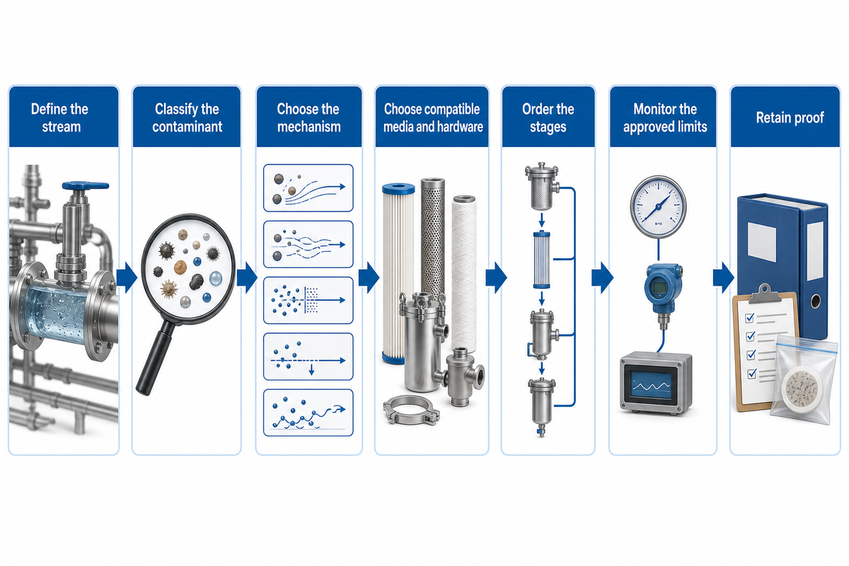
Stream-to-Barrier Filtration Map
- Define the stream: liquid or gas, normal and upset conditions.
- Classify the contaminant: particle, droplet, colloid, microorganism, dissolved ion, organic molecule, or vapor.
- Choose the mechanism: barrier capture, membrane separation, adsorption, ion exchange, gravity, or centrifugal force.
- Choose compatible media and hardware: rating, chemistry, geometry, seals, and housing.
- Order the stages: protect the sensitive and costly downstream step.
- Monitor the approved limits: pressure, outlet quality, integrity, exposure, or collector-specific indicators.
- Retain proof: result, trend, action, owner, residual route, and exception.
Write a one-line duty statement before comparing filters: “Reduce or remove [contaminant] from [stream] under [operating range] so the outlet meets [named requirement], verified by [method].” If any bracket is blank, equipment selection is premature.
Stop condition: “make it cleaner” is not an acceptance requirement. Define the contaminant and proof before debating filter type, pore size, or supplier.
2. Separate liquid, gas, and collection duties
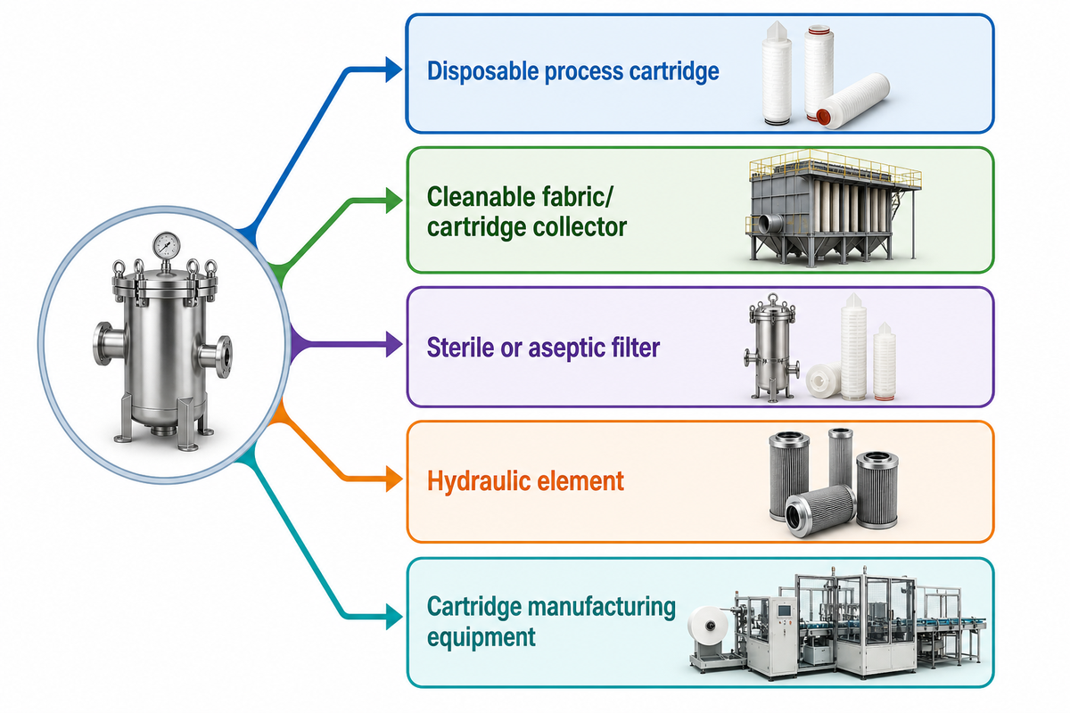
Liquid and gas systems both use staged protection and observe resistance to flow, but their carrier phase changes contaminant behavior, drainage, coalescence, re-entrainment, cleaning, and safety. Compressed-air coalescers, liquid depth cartridges, and pulse-cleaned dust collectors are not interchangeable simply because all contain filter media.
| Regime | Primary operating question | Do not import blindly |
|---|---|---|
| Disposable process cartridge | When has an approved limit been reached? | Collector cleaning cycles or sterile-release logic |
| Cleanable fabric/cartridge collector | Is cleaning and emissions control working? | Disposable-element changeout rules |
| Sterile or aseptic filter | Is validated integrity maintained? | Pressure-only replacement decisions |
| Hydraulic element | What performance is shown under the named test? | Universal use of hydraulic test results |
| Cartridge manufacturing equipment | Can the defined product be made and accepted? | Claims that the machine vendor designed the user’s process |
EPA notes that pulse-jet fabric-filter collectors usually remain online during cleaning and may be monitored through outlet particulate, leak detection, opacity, pressure differential, temperatures, gas flow, cleaning operation, and fan current. The DOE compressed-air sourcebook likewise treats pressure loss as an energy and system-performance issue, not a stand-alone proof of outlet quality.
3. Match the separation mechanism to the contaminant state
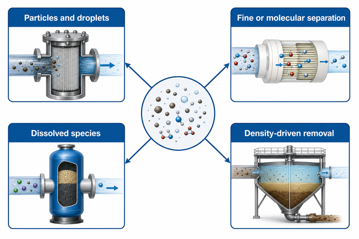
Industrial filtration types are best grouped by what they separate. Mechanical barriers retain particles or droplets; membranes separate by size and transport behavior; adsorption and ion exchange address selected dissolved species; gravity and centrifugal methods exploit density differences.
Particles and droplets
Screens, bags, cartridges, depth media, coalescers, cloth collectors.
Fine or molecular separation
Microfiltration through reverse osmosis, with feed and pressure conditions stated.
Dissolved species
Activated carbon, selective adsorbents, ion exchange, or another defined treatment.
Density-driven removal
Clarification, settling, flotation, cyclones, and centrifuges.
What are the different types of industrial filtration?
There is no single correct count because lists mix mechanisms, equipment shapes, media, and industries. One practical classification is mechanical barrier filtration, membrane separation, adsorption or ion exchange, and gravity or centrifugal separation; a treatment train may use several at once.
Micron-rating caution: two filters carrying the same micron number may use different rating bases, media structures, test methods, efficiencies, and operating conditions. “Finer” is not automatically better if it creates avoidable pressure loss, rapid plugging, or the wrong chemistry.
4. Use the Contaminant-to-Stage Decision Grid
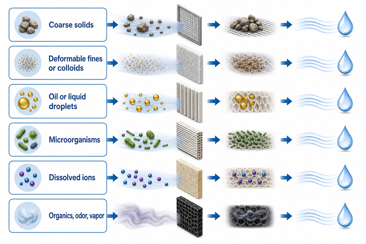
The first barrier should remove the load it can handle economically while protecting the next stage. The polishing stage then addresses what remains, and its verification method must correspond to the actual outlet requirement.
| Contaminant | First barrier to evaluate | Possible polishing | Proof question |
|---|---|---|---|
| Coarse solids | Screen, strainer, settler | Bag or cartridge | Loading and particle result |
| Deformable fines or colloids | Condition-specific depth or surface stage | Membrane where justified | Breakthrough and pressure trend |
| Oil or liquid droplets | Separator or coalescer | Fine coalescing stage | Carryover at stated flow |
| Microorganisms | Validated pretreatment | Validated membrane or disinfection | Integrity and microbial method |
| Dissolved ions | Pretreatment for solids | Ion exchange or membrane | Named chemical analysis |
| Organics, odor, vapor | Particle protection if needed | Selected adsorbent | Breakthrough for target compound |
Compatibility is part of selection, not a later material check. Record fluid composition, cleaning chemicals, temperature, pressure, viscosity, flow, expected loading, seals, housing materials, media chemistry, and allowable extractables before approving the filter family.
5. Build a staged treatment train
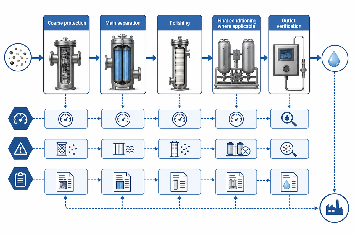
A common sequence is coarse protection, main separation, and polishing, followed by outlet verification. The point is not to maximize the number of stages; it is to keep the costliest or most sensitive stage from receiving a load it was not designed to handle.
Illustrative industrial-water train
Screening or sediment control → particulate filtration → membrane, adsorption, or ion exchange only where the contaminant requires it → disinfection or final conditioning where applicable → outlet verification.
Every arrow needs a reason: load removed, downstream risk reduced, pressure added, waste created, and measurement retained. An extra stage that has no defined contaminant or outlet contribution may only add pressure loss, maintenance, and spent media.
What is the most effective water filtration method?
There is no most-effective method independent of the feed and required outlet. Sedimentation or screening can remove large solids; depth media can handle selected particulate loads; membranes can separate finer particles or dissolved species within their stated range; activated carbon targets selected organics; ion exchange targets selected ions; and disinfection addresses microbial risk rather than suspended solids.
Design question: which contaminant must be reduced, to what stated level, at what flow and temperature, with what recovery, residual, cleaning, and verification burden? The answer determines the method.
6. Monitor disposable cartridges with three approved signals
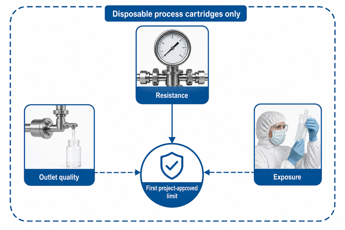
Scope boundary
The Three-Signal Changeout Rule is an editorial house heuristic proposed here for disposable process cartridges—not an industry, regulatory, or UDTECH rule. It never replaces a validated sterile-filter integrity program, a manufacturer or process-authority interval, cleanable-collector monitoring and cleaning logic, or site safety procedures.
Within that narrow scope, act when the first project-approved limit is reached for pressure loss, outlet-quality deterioration, or validated time, throughput, or service exposure. The approved limit must come from the system design, product specification, validation plan, manufacturer or process authority, or applicable standard.
1. Resistance
Track pressure loss at comparable flow, temperature, and fluid condition.
2. Outlet quality
Track the contaminant or quality measure that the stage must control.
3. Exposure
Track an approved time, throughput, cycle, or chemistry limit where applicable.
A peer-reviewed depth-filtration study illustrates why the signals should not be collapsed: flux, pressure, maximum throughput, and impurity breakthrough behaved as related but distinct observations under its specific conditions. Its numerical endpoint is not a universal cartridge limit.
Minimum monitoring record: signal; approved limit; operating condition; trend; measurement method; action; owner; and any exception regime. Even an intact-looking cartridge can suffer bypass, breakthrough, channeling, or chemical incompatibility.
7. Diagnose the failure pattern before replacing the system
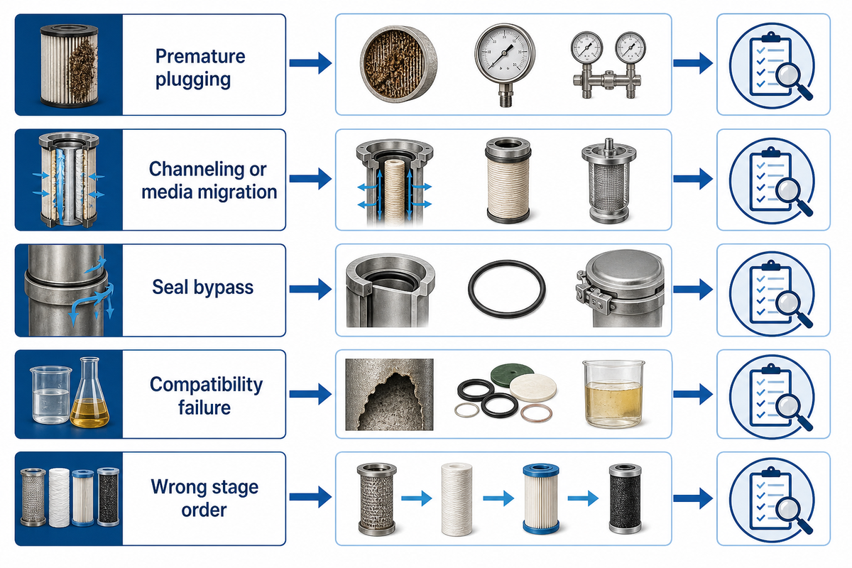
Premature plugging, channeling or media migration, seal bypass, chemical or temperature incompatibility, and wrong stage order require different checks. A 2024 clogging review reports that pore size, particle size, and feed density can change how clogging develops, so a smaller pore is not a complete diagnosis.
| Pattern | Checks | Containment or decision |
|---|---|---|
| Premature plugging | Actual loading, flow, viscosity, upstream stage, differential-pressure measurement | Correct the load or stage order before resizing |
| Channeling or media migration | Flow transients, media condition, supports, installation, outlet solids | Quarantine affected output and investigate |
| Seal bypass | Gasket, housing, seating, orientation, deformation, integrity result | Restore the sealing basis; do not blame media alone |
| Compatibility failure | Chemistry, temperature, cleaning agent, exposure time, material change | Stop exposure and obtain material review |
| Wrong stage order | Load reaching the final stage and missing pretreatment function | Repair the train instead of repeatedly changing the final filter |
Safety stop: combustible dust, ignition sources, deflagration isolation, grounding, hazardous captured material, or an unknown spent-media classification are not ordinary troubleshooting items. Stop and use the site’s safety, environmental, and compliance process.
Match the evidence package to the application
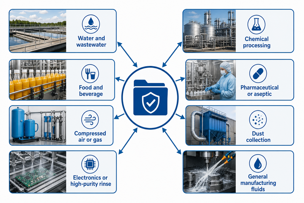
The outlet can look clear and still fail a chemical, microbial, compressed-air, or regulated-use requirement. Application evidence must therefore follow the contaminant, intended use, and governing quality system.
| Application | Evidence that can change | Residual to plan |
|---|---|---|
| Water and wastewater | Particle, chemical, microbial, recovery, discharge | Backwash, sludge, concentrate, spent media |
| Chemical processing | Compatibility, temperature, extractables, product loss | Contaminated cartridges and cleaning fluid |
| Food and beverage | Materials, sanitation, microbial controls, retained records | Product-bearing media and sanitation waste |
| Pharmaceutical or aseptic | Validation, integrity, sterilization, bioburden, deviations | Controlled product and cleaning residuals |
| Compressed air or gas | Particles, oil, water, pressure loss, dew point where relevant | Drained liquids and spent elements |
| Dust collection | Emissions, cleaning, leakage, ignition and explosion risk | Captured dust and fire/explosion controls |
| Electronics or high-purity rinse | Ions, particles, organics, microbial control, point-of-use quality | Regeneration waste, concentrate, spent elements |
| General manufacturing fluids | Particulate load, oil, coolant chemistry, tool or product protection | Used fluid, captured solids, contaminated media |
| Common wording | Boundary to record | Decision it should support |
|---|---|---|
| Water treatment, water purification, or a water filtration system | State whether water is used for process duty, high purity service, food and beverage processing, or municipal water; “pure water” is not a method. | Define water quality, taste and odor, chemical treatment, and residual targets before water goes to the next user. |
| Industrial water filtration, a sand filter, activated carbon filters, or membrane filtration | Say what is used to remove impurities and contaminants: suspended solids, selected organics, ions, or microorganisms. | Choose between depth media, ultrafiltration, nanofiltration, or another specific filtration step without implying one universal purification train. |
| Filter systems, membrane filters, or a semi-permeable membrane | Record flow rate, pressure drop, filtration efficiency, filter housing, and what happens within the filter at stated conditions. | Determine whether the filters used remove contaminants, remove impurities, or separate impurities and contaminants from liquids or gases. |
| Polypropylene, cellulose, plastic, or another medium | Record chemical resistance, corrosive exposure, temperature, high surface area claims, seals, and compatibility with cleaning. | Support selecting the right media instead of assuming a material name will increase filtration or prevent a clog. |
| Filters used in the pharmaceutical industry, oil refineries, or air-quality service | Name pharmaceutical products, whether the process must sterilize or support removing bacteria, and which environmental standards or air quality limits apply. | Show how filtration plays a role across various industries without claiming that one efficient method is automatically energy-efficient or sufficient for ensuring safety. |
For aseptic processing, FDA inspection guidance says filter replacement intervals and integrity-test procedures should follow the manufacturer or process authority, and loss of integrity is a process deviation. For hydraulic elements, ISO 16889:2022 has a specific multi-pass test scope; it should not be presented as a universal standard for every industrial filter.
Turn process requirements into a Process-to-Production Handoff Brief
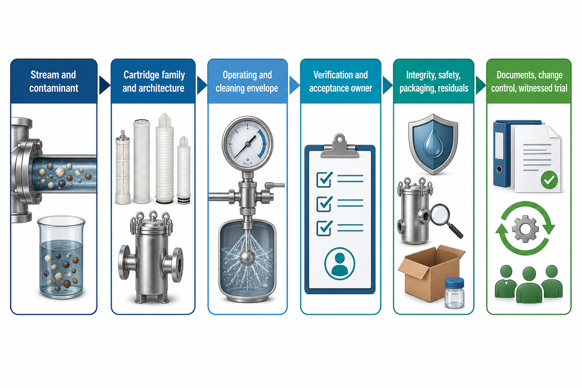
Using a cartridge and manufacturing that cartridge are different scopes. Move into production-line planning only after the cartridge family, material, geometry, operating envelope, verification method, traceability, residual route, and acceptance owner are defined.
Process-to-Production Handoff Brief
- Stream and contaminant form the cartridge is intended to address
- Cartridge family, material, geometry, media architecture, end treatment, and variants
- Operating and cleaning envelope relevant to material selection
- Product verification method, sample identity, traceability, and acceptance owner
- Integrity, hygiene, safety, packaging, and residual-disposal requirements where applicable
- Target documents, change control, witnessed trial basis, and unresolved assumptions
Once that brief is approved, route line configuration to the exact filter cartridge production line page or compare broader filter cartridge production line solutions. The PP depth-cartridge project can then review the PP melt-blown filter cartridge production line in the context of the defined product—not as a substitute for process design.
For media-architecture context, see the guide to gradient-density melt-blown filter cartridges. Before ordering, use the production-line scope readiness checker, then bind the project to witnessed evidence through a PP melt-blown production-line acceptance test.
About Suzhou UDTECH Technology Co., Ltd.
UDTECH manufactures PP melt-blown, CTO activated-carbon, and wire-wound filter production equipment. The company reports independent R&D and testing resources, a 6,000 m² standardized workshop, ISO 9001:2015 and EU CE certification, and equipment exports to more than 55 countries; project-specific performance remains subject to the signed configuration and acceptance evidence.
What current filtration trends change a buyer’s decision?
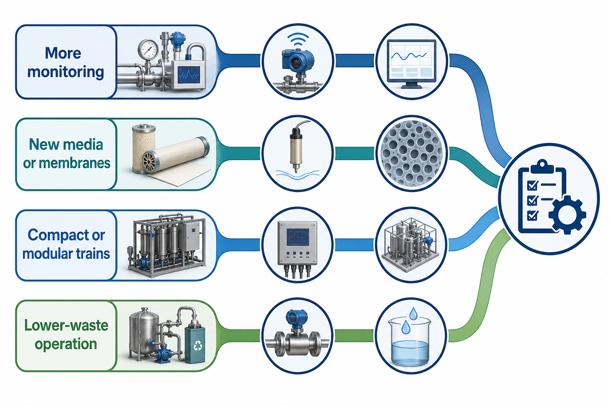
A trend matters only when it improves evidence quality or lowers a defined operating burden under the actual stream. Smart monitoring, new media, compact modular trains, and lower-waste operation are useful screening questions—not proof of compatibility, reliability, or lifecycle cost.
| Direction | Buyer question | Proof required |
|---|---|---|
| More monitoring | Does the signal predict an approved quality or maintenance decision? | Validated signal, limit, alarm, action, and data ownership |
| New media or membranes | Does it tolerate the real chemistry and cleaning cycle? | Comparable testing and compatibility evidence |
| Compact or modular trains | Which redundancy, access, and upset protections changed? | Layout, maintainability, isolation, and recovery review |
| Lower-waste operation | Was waste reduced or merely concentrated elsewhere? | Mass balance, cleaning use, spent-media and residual route |
Treat market forecasts as background, and keep technology examples narrowly attributed. A promising membrane or monitoring platform can justify a trial, but only representative testing and an approved acceptance basis can justify a process change.
Ready to translate a cartridge requirement into production-line scope?
Bring the cartridge family, material, geometry, variants, verification plan, utilities, traceability, and acceptance evidence—not just a micron label.
Frequently asked questions
What are the four types of filtration?
Four-part lists vary because they mix mechanisms and equipment. One useful industrial grouping is mechanical barriers for particles or droplets, membrane separation for finer or dissolved targets within a stated range, adsorption or ion exchange for selected dissolved species, and gravity or centrifugal separation for density-driven removal. A real industrial filtration process may combine all four, so the contaminant and required outlet matter more than the count.
What are the seven stages of water filtration?
Seven stages are a system design choice, not a universal industrial standard. An illustrative train might use screening, sediment control, coarse particulate filtration, finer particulate filtration, treatment for selected dissolved species, disinfection or final conditioning, and outlet verification. Each stage needs a stated feed problem and acceptance purpose; adding stages without those reasons can increase pressure loss, maintenance, and waste.
What is a three-stage filtration system?
Three-stage systems commonly mean coarse protection, main removal, and polishing. The first stage reduces load, the second performs the principal separation, and the third protects the outlet requirement. The actual mechanism can be a screen, bag, cartridge, membrane, adsorbent, ion exchanger, coalescer, or another process, so “three-stage” alone does not establish performance.
When is a cartridge filter a better fit than a bag filter?
A cartridge may fit when the required retention, media structure, housing, cleanliness, and verification favor that format. A bag may fit higher solids loading or simpler changeout in some duties. Compare both under the same flow, contaminant, rating basis, pressure, labor, disposal, and outlet requirement.
Does rising differential pressure always mean the filter should be changed?
No. First confirm that the reading is valid and compared at appropriate flow, temperature, viscosity, and valve conditions. For disposable process cartridges, rising pressure can be one project-approved changeout signal alongside outlet quality and validated service exposure, but the limit must come from the system design, product specification, validation plan, manufacturer or process authority, or applicable standard. Cleanable collectors may require cleaning-system and emissions indicators, while sterile filters may require scheduled replacement and integrity testing. Investigate bypass, breakthrough, channeling, and chemistry changes even when pressure appears acceptable.
References & Sources and scope notes
- US EPA Industrial Wastewater Treatment Technology Database: treatment technologies
- US EPA: monitoring fabric filters
- US FDA: aseptic processing and packaging inspection guide
- Peer-reviewed depth-filtration study
- Review of filtration clogging mechanisms
- ISO 16889:2022 public scope
- DOE Compressed Air Systems Sourcebook
This article provides process-planning guidance, not a project design, validation protocol, regulatory opinion, disposal classification, or product-performance guarantee. Application-specific engineering, safety, quality, laboratory, environmental, and process-authority decisions remain with the responsible organization.
Reviewed for Suzhou UDTECH Technology Co., Ltd. by XCX.