Get in touch with Suzhou UDTECH Technology Co., Ltd. Company

How to Set Up and Validate a Carbon Block Filter Wrapping Machine

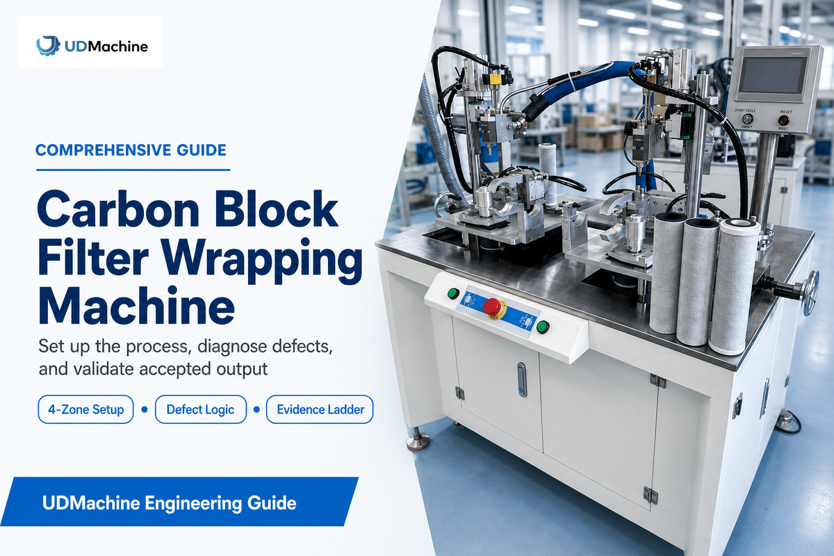
A Carbon Block Filter Wrapping Machine is production equipment that presents a formed carbon block, feeds and guides the specified wrap, controls coverage and overlap, cuts the material, holds the seam using an approved method, and releases the wrapped part. It can make those operations repeatable and traceable. It cannot, by itself, prove contaminant reduction, pressure drop, structural integrity, or service life. Those are finished-filter questions that require separate, claim-specific validation.
Updated September 2026 · Written by Cherry · Reviewed for process, measurement, and safety boundaries
TL;DR
- Prior to setting a recipe, define the carbon block, wrap, seam method, and acceptance criteria.
- Analyze the process in four zones: block presentation, web handling, coverage/seam, and cut/discharge.
- Don’t use higher tension as a default solution for wrinkles or drift.
- Divide the machine records, measurement validity, wrapped-part evidence, and finished-filter validation.
- Keep price, model configuration, delivery, and quotation decisions on the existing solution page.
What Does a Carbon Block Filter Wrapping Machine Control?
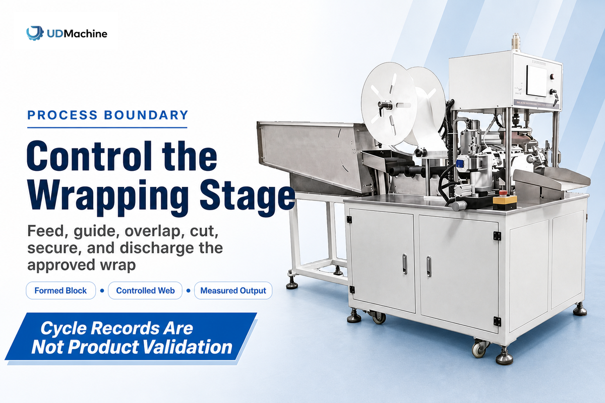
The machine controls a wrapping process around an already formed activated carbon block. Depending on the design, the sequence can include loading or feeding the block, presenting it on a stable axis, unwinding nonwoven fabric or another approved material, guiding the web, maintaining a controlled pulling force, forming the wrap, creating the required overlap, cutting the material, securing the seam, and discharging the part. An automated system can save recipes, monitor process sensors, count rejects, and exchange production line signals.
That description specifies an important boundary within the broader filter cartridge assembly process. Wrapping shouldn’t be confused with the upstream CTO activated carbon process, including extrusion, grinding, mixing, molding, or sintering. Wrapping shouldn’t be confused with the definitive proof that a water filter cartridge removes a specific contaminant. One patent for a carbon-block construction describes nonwoven scrim and fabric that are cut and wrapped around a carbon sleeve and held in place by net wrap. That shows that wrap layers can be structural components of a cartridge, but it isn’t a complete bill of materials.
Key boundary: a cycle-complete signal can show that monitored machine steps have been executed. However, a cycle-complete signal doesn’t necessarily mean the wrap is centered, the overlap is inside the product requirement, the seam will hold during subsequent assembly, or the finished filter fulfills the performance requirement.
Cycle records show what the machine monitored; product validation proves what the finished filter can do.
Process-validation principle used in this guide
If your project is already at model selection, line integration, FAT planning, or quotation, use the UDMachine carbon block filter wrapping machine solution page. This guide focuses on the engineering side of that handoff, what inputs are needed, what defects are traced, and what evidence is required.
Define the Carbon Block and Wrap Before Setting a Recipe
Recipe settings have meaning only when they are tied to a released product configuration. “Ten-inch CTO filter” is not enough. After parts begin to vary (e.g., two blocks that are drawn to be the exact same length), there may be differences in diameter, straightness, surface friability, end conditions, level of dust, density distribution, and dimensional variation. Two nonwoven rolls may differ in width, thickness, longitudinal and transverse stretch, friction, stiffness, direction, edge conditions, splices, and the history of the rolls. These differences all affect how the web behaves, the amount of stretch, and where the cut edge falls.
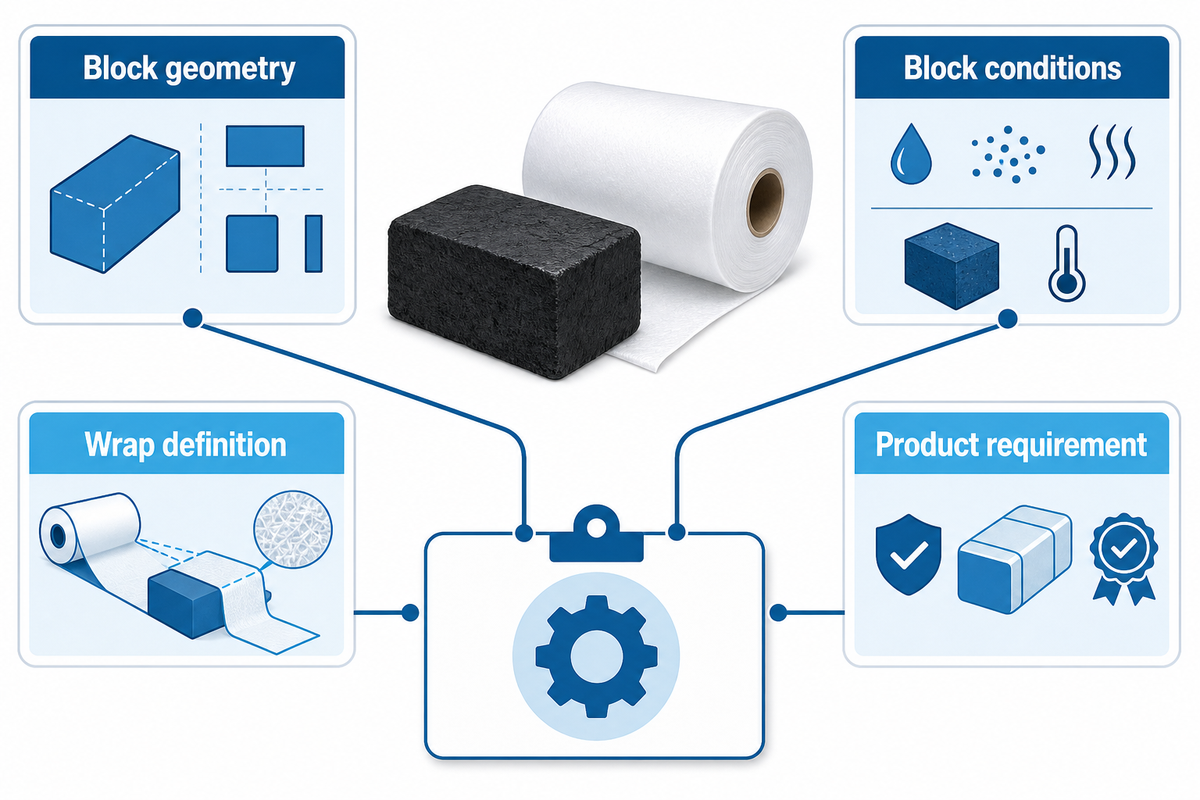
Freeze the input package in four groups:
- Block geometry consists of the released drawing(s), length and diameter ranges, straightness, concentricity, end-face condition, allowable chips and datum for loading and inspection.
- The block conditions include surface dust, condition of the surface (fragility), temperature, storage, lot identity, and handling conditions as well as any difference between a sample and production material.
- Wrap definition: material grade, supplier, lot, width, thickness, orientation, roll core diameter, maximum roll size, winding direction, splices, edge quality, and storage condition.
- The product requirement includes the coverage zone, nominal and permitted overlap, end clearances, seam retention, visual limits, handling checks, downstream capping interface, and the approved release test.
Don’t interpret a supplier demonstration as a formal specification. Published competitor data may include a filter-size range, cloth width, or cycle time for one model. In that case, the published numbers describe that supplier’s offering in line with its assumptions. They do not establish the correct web tension, overlap, or output for your carbon filter cartridge. If your team uses “CTO carbon” as an umbrella label for the product family, clearly describe the attributes of the block and the wrap prior to any trial work.
The same applies with the behavior of materials. A nonwoven may track well at one humidity, roll diameter, and line speed but behave differently after storage or a supplier change. Note the lot and the condition when a sample is approved. In case of a change of the material, the old recipe might be helpful, but it can’t guarantee that the process is still capable.
Use the 4-Zone Wrapping Process Map
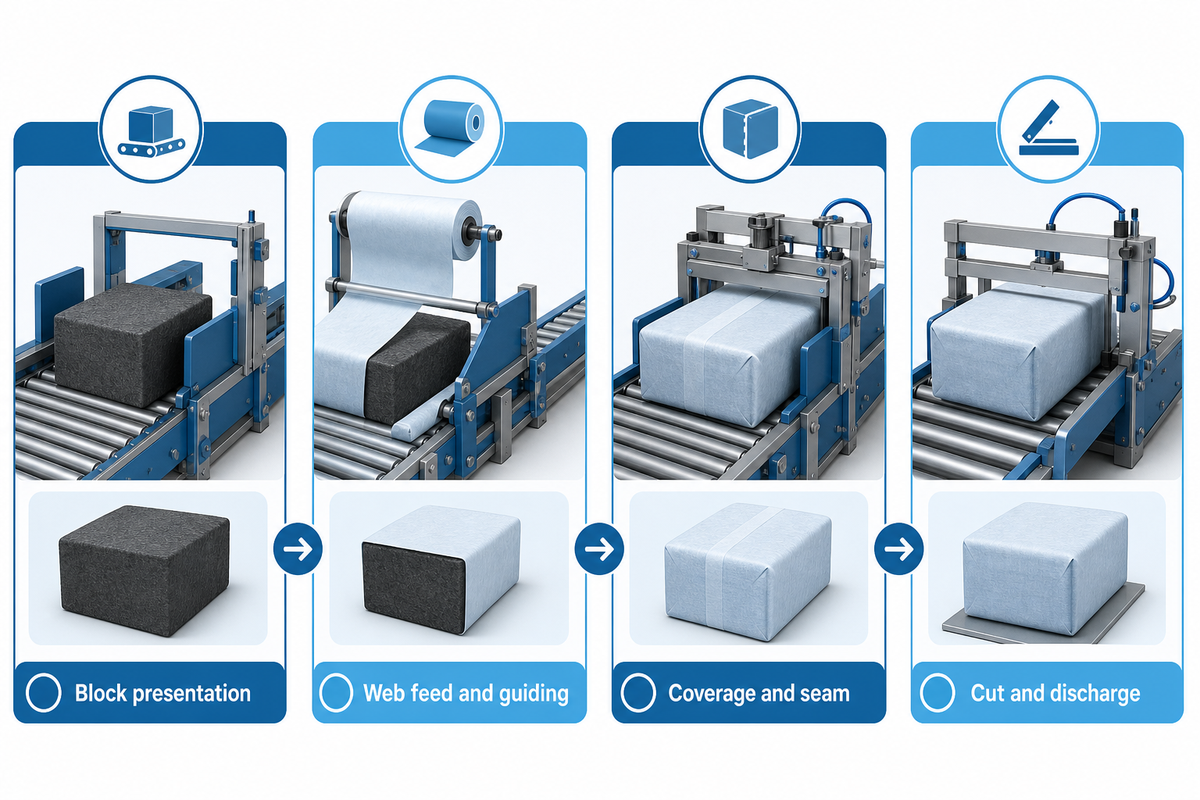
The Four-Zone Wrapping Process Map uses a Four-Zone Wrapping Process to organize the variables. It isn’t a statement to claim the machine has four variables. The team is prompted to examine the internals of each zone as the product is traced through the process.
| Zone | What must be controlled | Evidence to retain |
|---|---|---|
| 1. Block presentation | Part identity, axis, centering, support, rotation, end datum, clamping force, and surface damage | Part lot, fixture/setup ID, first-piece position check, chip or dust observations |
| 2. Web feed and guiding | Roll loading, unwind torque, tension, guiding, roller alignment and geometry, nip behavior, wrap angle, friction, support spans, and material profile | Roll lot, thread path, guide position, tension method, roller/blade condition, startup observations |
| 3. Coverage and seam | Lateral position, circumference coverage, overlap, seam location, adhesion/weld/net retention, edge curl, and downstream interface | Measured overlap and end clearance, full-circumference visual check, seam handling result |
| 4. Cut and discharge | Cut position, blade/heat condition, edge quality, retained tension during cut, release timing, transfer contact, and drop or collision damage | Cut-edge check, blade-life record, discharge observation, contained rejects |
The second zone deserves more attention than a single tension setpoint. Web-handling specialists list poor machine alignment, poor roller geometry, poor web quality, roller deflection, web expansion, unsupported spans, and improper tension as separate causes of wrinkling. Both excessive and insufficient tension can create problems. A web can also drift because a roller isn’t square, one side of the material has a different profile, or the block isn’t presented on the expected axis.
For this reason “increase tension” shouldn’t be an automatic answer. This may flatten one section of the web, but could lead to stretching the wrap, curling an edge, deflecting a roller, polishing a fragile block, or changing the seam after discharge. Determine where the issue first appears. Assess the upstream condition before changing the downstream symptom.
Build a Repeatable Setup and Changeover Method
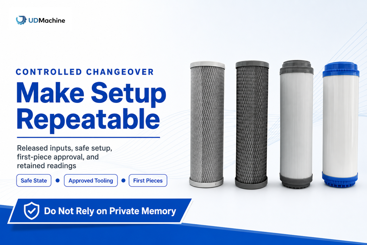
Successful changeovers begin with fully released inputs and end with documented first-piece approval. It should be executable by another trained operator without relying on a private memory of “where the knob usually sits.”
- Remove the previous job. Remove all previous materials, labels, samples, and recipe. Ensure the machine is in the safe state as outlined in procedure.
- Confirm new inputs. Verify the block and wrap match the work order. Ensure the roll edges, splices, and block ends aren’t visibly contaminated or damaged.
- Place product hardware. Fit and identify the approved guides, supports, mandrels, clamps, cutters, or seam tooling. Confirm their position and condition.
- Thread and center the web. Follow the documented path, winding direction and wrap angle, guide datum, and nip position and condition. A photo can supplement the instructions but shouldn’t be a substitute for a set of physical dimensions.
- Load the controlled recipe. Confirm permissions, revision and product mapping. Document any authorized offset rather than editing the master value.
- Run a dry or low-risk check. Verify sensors, motion, guarding, interlocks, cutting, and discharge before releasing production material where the machine design permits it.
- Approve the first pieces. Inspect the full circumference, both ends, overlap, seam, cut edge, block condition, and downstream fit. Record the actual measurement and don’t substitute an average measurement or a PASS.
- Monitor the transition. During startup, define when normal sampling begins. Startup conditions can differ from steady-state operation as roll diameter, friction, temperature, dust, and operator handling settle.
A golden sample only serves its purpose if its identity and function are established. A sample that’s faded, compressed, or dust-loaded beside the machine can be a misleading visual standard. Protect it, date it, connect it to the drawing and approved process, and replace it through change control. Where visual appearance is not enough, use measured reference data or a physical gauge suited to the requirement.
After changeover, preserve the individual readings used for approval. A single average overlap can hide one exposed end and one excessive seam. Sampling position also affects inspection; inspect the circumference and length at locations defined by the product plan. The measuring system must be able to resolve the specified tolerance.
Diagnose Wrapping Defects Without Chasing One Setpoint
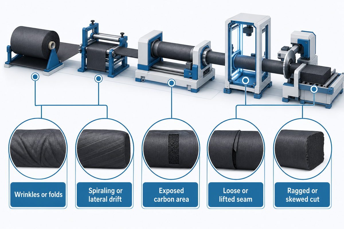
Restrict the output of the affected process prior to any changes to the process. Assign the likely cause as material, setup, mechanical, control, or downstream handling, etc. Local corrections can conceal greater impacts.
| Defect type | First checks | Controlled response |
|---|---|---|
| Wrinkles or folds | Where the wrinkle begins; roll quality; roller alignment/geometry; nip; unsupported span; tension stability; block axis | Hold output, correct the verified cause, then repeat full-circumference first-piece inspection |
| Spiraling or lateral drift | Guide datum, roll loading, unequal edge profile, angled entry, roller square, block centering, side contact | Restore alignment before using tension or guide offsets to compensate |
| Exposed carbon area | Wrap width, lateral drift, overlap, cut position, block diameter/length, seam opening after discharge | Separate width/position causes from seam-retention causes and verify both ends |
| Variable overlap | Material stretch, circumference variation, feed length, slippage, sensor repeatability, recipe/product mismatch | Compare individual measurements by position and time; do not approve from an average alone |
| Loose or lifted seam | Approved retention method, surface dust, heat/adhesive condition, pressure/time, overlap, handling before set | Contain, verify material and process window, then repeat the defined seam check |
| Ragged or skewed cut | Blade or hot-cut condition, web motion during cut, guide position, contamination, material orientation | Service or replace the qualified tool; confirm cut position and edge integrity |
| Chipped or marked block | Clamping/support force, misloading, abrasive contact, tension, transfer collision, drop height, block condition | Protect the block first; restore datum and handling before increasing production speed |
| Dust carryover | Incoming block condition, abrasive contact, cutter action, cleaning interval, local capture, transfer disturbance | Evaluate the actual material and task hazard; correct generation and containment under the site plan |
| Good at startup, poor later | Roll diameter/torque change, heat buildup, dust accumulation, blade wear, friction drift, sensor contamination | Trend readings over time and define maintenance or sampling triggers from evidence |
When possible change one verified cause at a time. Record the original condition, the change, the parts affected, the new first-piece evidence, and the disposition of held output. When several changes are made together, the wrapping machine may produce acceptable-looking output even though the team may not understand which mechanism changed.
Inspect beyond the wrapping machine. A capping station can create a seam disturbance; a transfer guide can mark the block; storage can compress a soft wrap; a downstream heat process can affect the retention method. The location of final inspection defects may not be the location where the cause occurred.
Validate the Process with the Wrapping Evidence Ladder
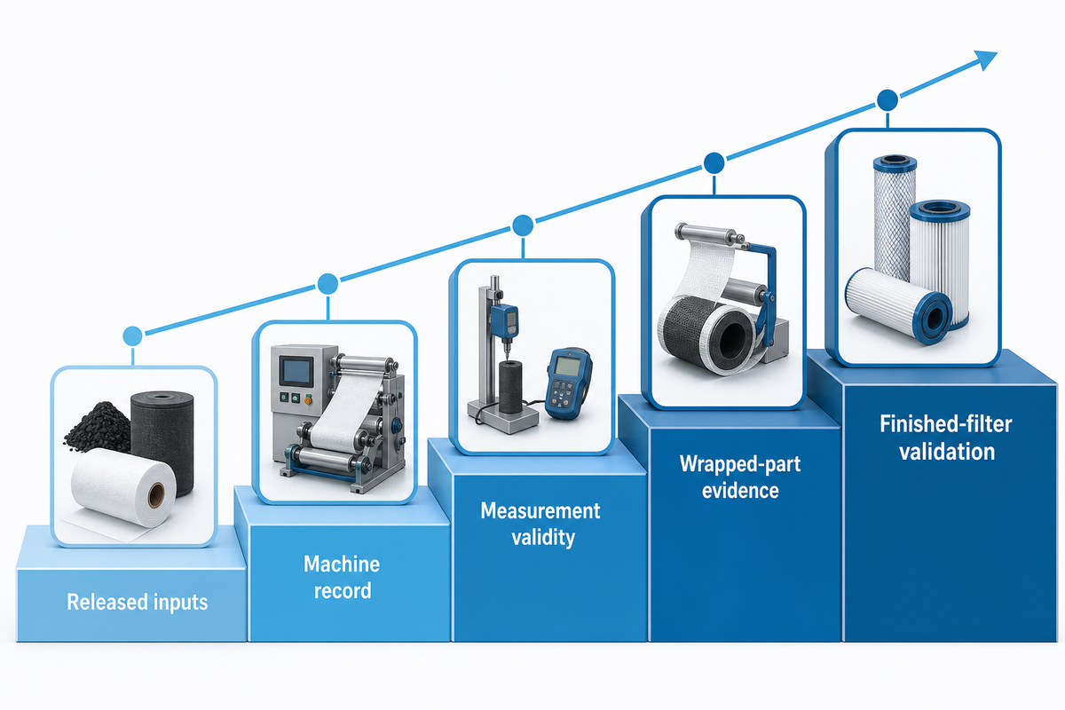
The Wrapping Evidence Ladder distinguishes what the machine knows from what the product must demonstrate. A valid result at one level isn’t sufficient to close the next level.
| Evidence level | Question answered | What remains open |
|---|---|---|
| 1. Released inputs | Were the correct block, wrap, tooling, and recipe revision used? | Whether the machine executed correctly |
| 2. Machine record | Did monitored motion, sensors, settings, alarms, and cycle states meet the programmed conditions? | Unmonitored position, actual geometry, seam result, and block damage |
| 3. Measurement validity | Were instruments suitable, positions representative, sample counts defined, and individual readings retained? | Whether the measured wrapped part predicts downstream performance |
| 4. Wrapped-part evidence | Do coverage, overlap, seam, edge, handling, and appearance meet the released requirement? | Finished-cartridge integrity, safety, and claim-specific performance |
| 5. Finished-filter validation | Does the complete cartridge pass the approved tests for its intended application? | Performance after unvalidated material, recipe, tooling, or process change |
The measurement-validity level is easy to skip. A caliper might not work with a compressible overlap. A camera may need defined lighting, angle, and calibration. A seam-handling check may also need a constant direction and force applied uniformly. Samples collected only after a knowledgeable technician adjusts the line aren’t indicative of ‘normal’ start up. Record the sampling location, time, product lot, roll lot, recipe, operator intervention, and the raw readings used in the decision.
The validation of finished filters isn’t a single blanket test. Structural integrity, material safety, pressure or flow behavior, and a stated contaminant-reduction claim can require different evidence. The dimensions important to the customer and the product specification define what needs to be validated. The wrapping machine should make it possible to trace a filter back to the process conditions, but it cannot define or certify every downstream test.
Use challenge samples in a controlled manner. Test the approved block sizes and wrap lots. Include justified edge conditions. Evaluate startup, steady state, planned stops, restart, splicing, roll changes, and changeovers. The purpose isn’t to introduce a failure. It’s to understand if the controls and checks can identify a significant change prior to the release of nonconforming product.
Maintain the Machine and Control Dust Safely
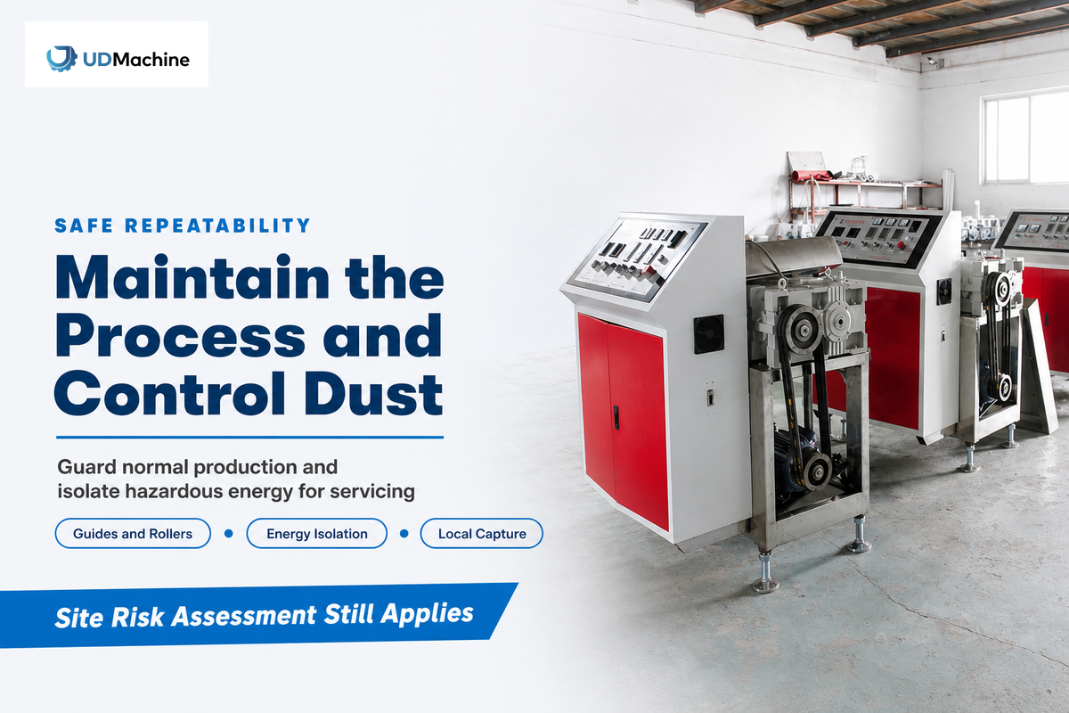
Maintaining Repeatability. Add controls to mechanisms that can alter the process. This includes the guiding surfaces and roller adjustments, roller surfaces and bearings, nips, clamps and support structures, sensor cleanliness, condition of cutting tools, seam and extraction tooling, guards, mechanical interlocks and transfer contacts. Use actual conditions and defect trends to establish intervals. Don’t wait for visible failure to dictate every requirement.
Machine guarding and lockout/tagout deal with different operating conditions. OSHA guidance distinguishes safeguarding during normal production from hazardous-energy control during servicing or maintenance that may expose workers to hazards. When considering a wrapping system, the in-running nip points, rotating shafts and transmissions, clamps, cutters and hot-cut devices, pneumatic energy, and spring energy are all potential hazards. Unexpected startup and reaching into the wrapping system to clear a jam also require consideration.
Safety measures may differ with tasks and machines. Some tasks such as normal loading or minor approved adjustments may use engineered safeguards and documented instructions. Blade changes, jam clearing, cleaning behind a guard, or scheduled maintenance may require shutdown, isolation of energy, release of stored energy, and confirmation within the site’s hazardous-energy program. Please refer to the machine manual, comply with applicable local laws, and perform a risk assessment by the employer; this guide shouldn’t be used in place of that risk assessment procedure.
Carbon-bearing dust also warrants an evidence-based assessment. OSHA’s combustible dust program includes coal and other carbon dusts, while its classification guidance emphasizes reliable material test data and the actual workplace condition. Don’t consider all carbon-block dust to be the same, and don’t assume it’s safe. Evaluate the material safety data, the generation of particulates, the enclosure, the ignition sources, static discharge potential, the ventilation system, local capture, and collection, the control and clearance system, the overall site housekeeping, and any required control and precautionary measures for working in a hazardous area.
Cleaning should control the hazard without creating another. Avoid methods that disperse settled dust unless it’s permitted in the formal procedure. Examine the extraction-system performance where provided, ensure dust doesn’t block sensors or contaminate seam surfaces, and record unusual dust accumulation. If a change in block formulation or modification of the cutting action results in increased dust, it should be subjected to a safety & process review rather than a housekeeping review.
When Does Wrapping Automation Make Sense?
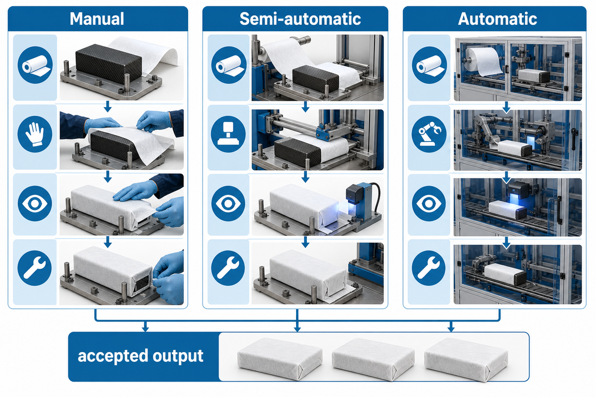
Automation makes sense when the process needs more repeatability, traceability, controlled operator exposure, or integration than the current method can provide, and when the product inputs and acceptance evidence are stable enough to validate the investment. Product inputs and evidence of acceptance must be stable enough to validate the investment. Automation doesn’t have a single volume or payback threshold.
| Production route | May fit when | Main evidence question |
|---|---|---|
| Manual | Volumes are low, variants change often, development is active, and skilled handling can be controlled | Can operator method, exposure, inspection, and traceability remain consistent? |
| Semi-automatic | A machine should control cutting, rotation, or tension while an operator loads, aligns, or approves parts | Which human decisions remain, and how are they error-proofed and recorded? |
| Automatic | Inputs are defined, repeatability and traceability matter, changeovers are manageable, and upstream/downstream interfaces can be controlled | Does the line sustain accepted output across startup, steady state, stops, roll changes, and product changeovers? |
Compare accepted outputs, not raw cycles. Include rejected and reworked parts, waste, block damage, roll and product changes, planned cleanings, interventions, maintenance, and downstream stops. If the machine runs quickly but the seam reopens at capping, the line hasn’t truly gained greater output.
Also consider the product mix. An automatic wrapping machine may be suitable for a stable product family, but may be a burden if the block size, length, and material change, along with the seam, the acceptance criteria, and the method of construction. In this case, semi-automation is likely the safer option, while the product is still developing. The actual sample trial and configuration review, framed by the UDMachine product-to-line fit screener, will make the call, not a generic blog ROI method.
Use a Requirement-First Acceptance Checklist
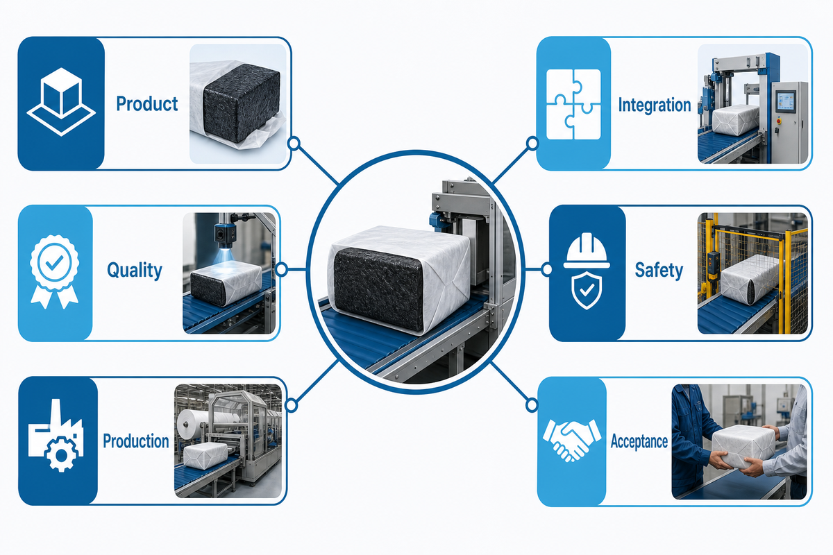
Before requesting a configuration, send the evidence needed to design and test the process.
- Product: block drawings, revisions, size range, tolerances, fragility, surface condition, samples, wrap specification, seam method, and downstream assembly.
- Quality: approved appearance, measurement locations, overlap and clearance requirements, seam/handling check, defect taxonomy, sampling, retest, and lot disposition.
- Production: accepted-output definition, variant mix, batch size, shifts, roll changes, startup and restart requirements, cleaning, maintenance, and traceability.
- Integration: upstream feed, downstream transfer, utilities, space, line signals, reject path, data exchange, backup/recovery.
- Safety: block and wrap safety data, dust information, ventilation or extraction, review of static or ignition, guards, hazardous energy procedures, ergonomics, training, and local needs.
- Acceptance: test samples and materials, FAT functions, measurement methods, instruments, sample count, allowed intervention, raw-data package, site checks, and final product-validation owner.
Define output as accepted wrapped blocks made under agreed conditions. State what happens during a roll splice, material lot change, sensor alarm, blade replacement, jam, restart and product changeover. A test that ignores these normal events can make an unstable process look capable.
This package should be moved to the existing solutions page for commercial specifications, model selections and a project quotation. Its role should be to clarify, not substitute, this discussion.
Ready to review your wrapping process?
Prepare the block drawing, wrap specification, accepted sample, defect criteria, output definition, and line interfaces. UDMachine can then discuss a configuration against real inputs instead of a generic machine description.
Frequently Asked Questions
What does a carbon block filter wrapping machine do?
It presents a formed carbon block, feeds and guides an approved wrap material, controls its position and pulling force, creates the specified coverage or overlap, cuts the material, retains the seam by the approved method, and discharges the part. It may also save recipes and production records. It doesn’t by itself prove contaminant reduction, pressure drop, structural life, or the compliance of the finished filter cartridge.
How do you stop wrinkles and material drift during wrapping?
Contain the affected output and mark the first bad part. Watch a fresh web pass at reduced speed where the risk assessment and machine instructions permit it, then identify the zone where the wrinkle or sideways movement first becomes visible. Check roll loading, unwind brake or drive behavior, web path, guide datum, roller alignment and geometry, nip behavior, unsupported spans, tension stability, block centering, material profile, roll condition, cut timing, and discharge contact. Compare the current material lot and recipe with the last accepted run. Increasing tension isn’t a universal fix; it can add stretch, edge curl, roller deflection, loss of traction, or block damage. Change one verified cause at a time, document the adjustment, repeat first-piece approval, and retain the individual measurements before releasing contained output.
How much overlap should a carbon block wrap have?
There’s no defensible universal overlap for every carbon block and wrap. The value depends on block geometry, wrap width and behavior, seam-retention method, downstream capping or assembly, and the finished cartridge specification. Set the nominal and permitted range from the drawing or validation study, inspect the defined positions around the part, and preserve individual readings. A supplier example can guide a trial but shouldn’t become a release limit without approval.
Can machine alarms prove the wrapped filter is good?
No. An alarm only reports the conditions the machine actually monitors. Release still needs valid measurements, representative wrapped-part inspection, and any required finished-filter tests.
What causes exposed carbon after wrapping?
Possible causes include insufficient material width, lateral drift, incorrect block centering, a shifted cut position, variable block geometry, inconsistent feed length, excessive stretch, or a seam that opens after discharge or downstream handling. Confirm the symptom on contained parts, separate material and geometry causes from setup and mechanism causes, and verify both ends and the full circumference after the correction.
Does every carbon block wrapping machine need dust extraction?
Not automatically. Assess the actual material, dust generation, enclosure, ignition sources, work area, and applicable rules. If extraction is specified, verify capture, collection, housekeeping, static control, and maintenance.
What should be tested during FAT?
Write the FAT protocol before the visit. It should identify the approved block and wrap lots, sample quantity, product range, recipe conditions, warm-up and changeover rules, permitted operator interventions, measurement methods, acceptance limits, and raw-data deliverables. During the test, verify agreed machine functions, guarding and safety devices, alarms, emergency and restart behavior, recipe access, roll loading, web guidance, block presentation, cutting, seam retention, discharge, reject handling, traceability, and representative material runs. Record stoppages and adjustments instead of hiding them inside an average output figure. Test the agreed size changes, not only the easiest sample. Photograph or retain accepted and rejected examples when the plan permits it. FAT doesn’t automatically prove the buyer’s site utilities, upstream and downstream integration, long-duration reliability, or finished-cartridge performance; those items belong in site acceptance, capability work, or product validation as specified.
What should a buyer send before requesting a configuration?
Send block drawings and tolerances, the size range, photos and representative samples, the wrap specification and roll details, the seam-retention method, approved appearance and measurement criteria, the accepted-output definition, changeover expectations, utilities, safety constraints, traceability needs, and upstream/downstream interfaces. Identify any unknowns honestly so the supplier can plan trials instead of hiding assumptions inside a quotation.
About UDMachine
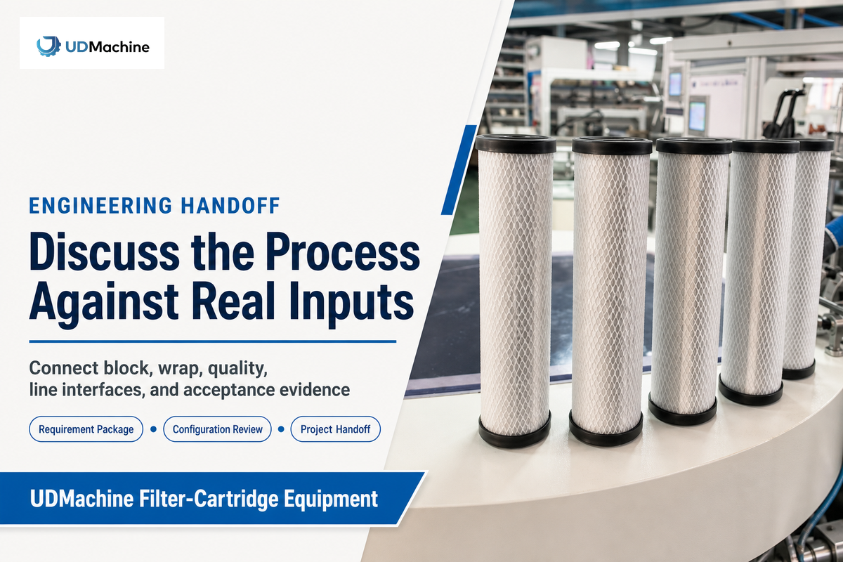
Suzhou UDTECH Technology Co., Ltd., operating as UDMachine, designs and supplies equipment for filter-cartridge manufacturing and assembly. Company identity is kept separate from product proof: the suitability of a wrapping process still has to be confirmed against the buyer’s block, wrap, line conditions, safety assessment, and acceptance plan.
References & Sources
- OSHA, Lockout/Tagout and machine-guarding interpretation.
- eCFR, 29 CFR Part 1910 Subpart O, Machinery and Machine Guarding.
- OSHA, Combustible Dust National Emphasis Program.
- OSHA, Classification of Combustible Dusts.
- Maxcess, The Top Seven Causes of Web Wrinkling.
- Dover Flexo Electronics, Nonwoven Fabric Manufacturing Tension Control.
- Google Patents, US6368504B1, Carbon Block Water Filter (construction history only).
- Filtration + Separation, Fabric Reinforcement of Nonwoven Filter Cloths.
UDTECH / ENGINEERING GUIDE
About UDMachine
UDTECH publishes practical production-line planning guides for filter cartridge making, assembly, finishing, and complete-line projects.
Use these guides to define cartridge type, process route, target output, available utilities, acceptance evidence, delivery scope, and installation constraints before selecting equipment.
Start with the cartridge
Media, diameter, length, end-cap format, and rated output define the real machine route.
Clarify the line scope
Utilities, layout, automation level, inspection points, and acceptance tests vary by project.
PRODUCT / CAPACITY / ACCEPTANCE
Prepare Your Line Brief
Product types
PP Melt Blown · String Wound · CTO Carbon · UDF Tube
Start with
Cartridge type · Target output · Country
Planning inputs
Utilities · Layout · Process · Acceptance standard
Response route
Submit the website inquiry form
Submit Project Brief