Get in touch with Suzhou UDTECH Technology Co., Ltd. Company

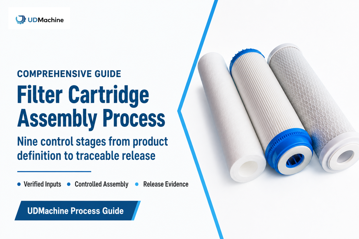
The filter cartridge assembly process is the controlled route that turns verified media, cores, cages, end caps, adapters, and seals into a traceable released cartridge. The process involves assembling cartridges via a controlled pleated route that can be adapted to other filter-element families, but the route is not universal for every cartridge.
Updated September 2026. Written by Cherry. Process, testing, and evidence boundaries reviewed.
TL;DR
- Set product definition and critical-to-quality inputs. Then, set stations and cycle goals.
- Control every handover. This includes the final test as well as material identity, geometry of the elements, joint formation, test method, and the lot record.
- Use the 9-Stage Control-Point Map as a model for planning, not as a standard or a list of machines.
- Separate process-window evidence, assembly evidence, and finished-filter evidence.
- An accepted good output must be defined before comparing production lines or running acceptance tests.
What the Filter Cartridge Assembly Process Includes
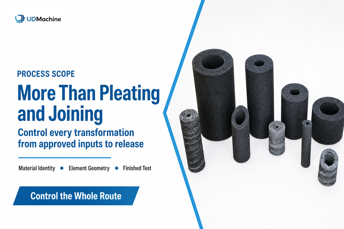
An assembly process extends beyond simply pleating and joining end-caps. An approved product definition is the start of the assembly. This control extends to approved incoming components and each transformation of the assembled component. The finished component must be verified with a defined method. Sufficient traceability must be available to support a release. The exact methods depend on the cartridge design.
For pleated cartridges, the physical route includes media slitting, layer alignment, pleating, control of pack length, formation of a longitudinal seam, and insertion of cores and cages. It also includes joining of end-caps or adapters, installation of seals, inspection, integrity testing, cleaning, marking, and packaging. Some operations are combined and/or grouped. Others may include curing, flushing, sterilization, or application-specific tests. Elements of media are formed differently for melt-blown and string-wound media.
The control point transfers idea is the ability for each member of the team to know what was input and verified, what variable can be changed, what evidence were they keeping, and what downstream error can failure create. This assists in removing the weak but familiar pattern of focusing on a final “PASS” signal to counter the absence of control for material, geometry, joint, or handling information.
If your product definition is already defined and you need configurations, specifications, commercial terms, or a quote, use the filter cartridge assembly process equipment page. For a more extensive comparison of equipment families, see the filter cartridge equipment selection guide.
Freeze the Product Definition and Critical-to-Quality Inputs
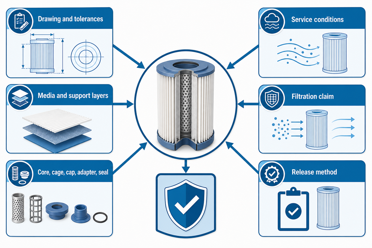
Before an assembly route can be controlled, the product and its acceptance basis must be defined. Freeze the current drawing, bill of materials, service conditions, critical-to-quality characteristics, and test method. If these remain in flux, a stable machine recipe may only produce the incorrect cartridge consistently.
| Input | What must be defined | Why assembly depends on it |
|---|---|---|
| Drawing and tolerances | Overall length, diameters, interfaces, joint geometry, datums, seal position, allowable deformation | Sets fixture, gauge, seating, cut-length, and dimensional-release requirements |
| Media and support layers | Material identity, grade, orientation, width, thickness, pore or retention claim, handling condition | Affects forming, pleat geometry, seam route, pressure drop, cleanliness, and test interpretation |
| Core, cage, cap, adapter, seal | Material, revision, dimensions, mating features, surface condition, approved supplier and lot | Controls fit, concentricity, compatibility, joining behavior, bypass paths, and traceability |
| Service conditions | Fluid, temperature, pressure, flow, chemistry, cleaning, sterilization, storage, and life expectations | Defines which materials, joints, seals, and evidence are relevant to the intended use |
| Filtration claim | Claim wording, test basis, challenge conditions, rating convention, and approved limit | Prevents a production check from being misrepresented as application-performance proof |
| Release method | Instrument, setup, calibration, sampling, raw result, limit, retest, and disposition rule | Makes pass/fail decisions reproducible and auditable |
Critical-to-quality inputs are product dependent. For some designs, the critical-to-quality characteristic may be pleat height. A weld feature, bondline, adapter position, or cleanliness condition may be critical for another design. The specification should therefore be clear about both the controlled characteristic and its measurement basis. “Correct height” is meaningless unless the drawing revision, unit, gauge method, sampling point, and decision limit are defined.
Define the filter material and intended duty before fixing geometry. The same manufacturing process cannot be assumed for an air filter, liquid filtration cartridge, gas filter, water treatment element, or high-temperature unit. For each type of filter, record the filter media, such as filter paper, polyester, PP, a quality membrane, or another material used, plus pore size, pore structure, surface area, filtration area, number of pleats, inner core, outer cage, O-ring, inlet, valve interface, and whether to perforate a cylindrical support.
The production process should also state how the filtration process changes among types of filter cartridges, including membrane pleated and high flow builds. The pleating machine, joining route, and quality control plan should be linked to the filtration system rather than selected from a generic station list. If the application requires microbial control or sterilization, define whether later operations sterilize the cartridge and whether the component is approved for reuse.
Connect the impurity challenge to higher flow rates and any claim of high filtration efficiency. The supplier should state which cartridges need to be replaced, what prefiltration is assumed, and which evidence applies across various industrial duties; buyers can then customise the acceptance plan without treating those examples as universal limits.
Do not treat reference documents as universal limits. ISO 2942:2018 discusses fabrication integrity and the first bubble point for hydraulic fluid power filter elements and ISO 16889:2022 explains a multi-pass method for evaluating hydraulic filter performance. Their scopes can inform related work, but they do not provide a single release plan for every water, air, food, pharmaceutical, or industrial cartridge.
Do: let the approved drawing, application, and validation plan govern. Do not: copy a convenient temperature, pressure, time, sample size, or integrity limit from a different cartridge family.
Use the 9-Stage Control-Point Map
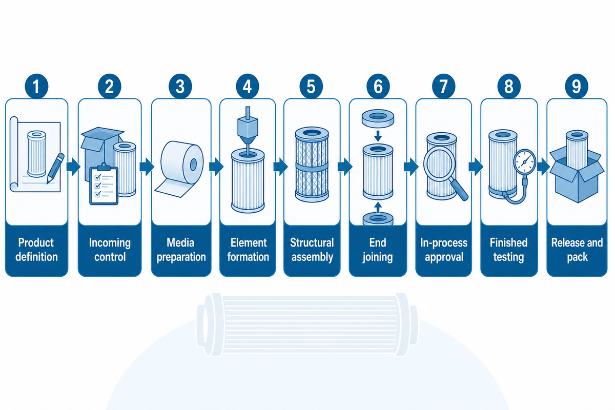
The map below is UDMachine’s editorial model for planning and diagnosis. It is not an ISO sequence, a regulatory requirement, or a claim that every line needs nine physical stations. Its goal is to make inputs, processes, evidence, and risks of propagation visible, even with combined or branched operations.
| Stage category | Verified input | Controllable variable | Minimum record | Failure propagated |
|---|---|---|---|---|
| 1. Product definition | Approved drawing, BOM, CTQs, intended use | Revision and change authorization | Released specification set | Wrong route or acceptance basis |
| 2. Incoming control | Media and component identity, condition, lot | Supplier release and quarantine | Lot and inspection status | Compatibility, fit, or performance variation |
| 3. Media preparation | Released roll or formed media | Width, orientation, tension, cleanliness | Material lot and preparation recipe | Damage, skew, contamination, wrong area |
| 4. Element formation | Prepared media and supports | Pleat or formation geometry, pack length | First-off and in-process geometry | Pressure-drop or fit variation |
| 5. Structural assembly | Pack, core, cage, seam materials | Alignment, seam, insertion, containment | Recipe, tool, and geometry result | Bypass, collapse, deformation, loose pack |
| 6. End joining | Caps, adapters, seals, assembled element | Energy, heat, adhesive, time, seating | Joint recipe and part lots | Leak, bypass, weak or distorted joint |
| 7. In-process approval | First-off and serial assemblies | Inspection frequency and disposition | Results, alarms, holds, authorization | Undetected drift into finished stock |
| 8. Finished testing | Conditioned complete cartridge | Method, setup, challenge, decision rule | Instrument, raw result, limit, disposition | False accept, false reject, unsupported claim |
| 9. Release and pack | Accepted unit and complete genealogy | Release authority, marking, protection | Lot release and packaging record | Mix-up, damage, or untraceable shipment |
Architecture-specific branches appear in the map. Pleated, melt-blown, string-wound, and carbon-block lines are examples of these. The control questions are useful, but their definition, measurement, and release mechanisms must be redefined for the product. A station checklist should never be substituted for a cartridge dossier.
The map also indicates regions of ownership transfer. An incoming inspection cap lot release, production joining the lot, quality approval of a first-off sample, and a finished test performed by a lab are examples of ownership transfer. Record the transfers. A defect can remain “between departments”, while suspect units continue to be processed.
Build the Element and Choose the Joining Route
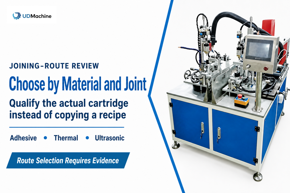
Element formation establishes the geometry that every subsequent operation inherits. Control media orientation, layer alignment, pleat or formation geometry, pack length, seam condition, core and cage fit, and handling. Then consider the end-joining approach based on the actual material compatibility, joint geometry, cleanliness, thermal load, cycle, and validation needs.
For a pleated element, examine more than the outer diameter. Look for uneven pleat pitch, collapsed channels, damaged media, a short pack, an open longitudinal seam, or forced cage insertion. Each may cause a change in flow distribution and a bypass path. If thermal or adhesive exposure follows, determine which areas need to be protected and which deformation is acceptable under the released drawing.
| Route | Potential fit | Variables to qualify | Boundary |
|---|---|---|---|
| Adhesive bonding | Dissimilar materials, gap filling, heat-sensitive constructions | Surface condition, grade, ratio, amount, placement, open time, seating, cure | A correct dispense does not prove adhesion or finished integrity |
| Thermal or infrared joining | Compatible thermoplastics with accessible melt interfaces | Heat profile, distance, time, surface melt, transfer, pressure, cooling | Protect media and control flash, distortion, and heat history |
| Ultrasonic welding | Compatible thermoplastics and joint features that transmit energy | Joint design, fixture, amplitude, energy or time basis, force, collapse | Material and geometry govern; there is no universal recipe |
| Mechanical retention | Designs with qualified snap, crimp, thread, compression, or locking features | Part tolerance, engagement, torque or displacement, seal compression | Retention and sealing evidence must match service loading |
TWI’s ultrasonic welding guidance links component design and weld parameters with a key constraint: performance of the weld depends on both the joint and the process. A recipe copied from another component can fail when the resin, energy path, fixture support, or interface geometry changes. Adhesive routes have the same level of dependency on the configuration, evaluation, surface, chemistry, bondline, and cure.
One published filter-cartridge construction patent shows an integration approach, but it is not an instruction for building a factory or an acceptance standard. Use the actual design and construction documentation. The guide for the end-cap gluing machine separates dispensing controls from bond and filter-level proof.
Control the Process Window and Lot Genealogy
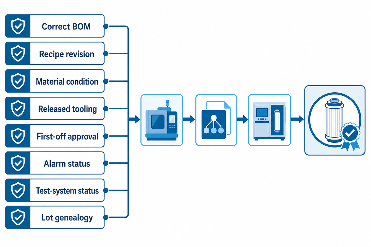
The process window links the settings which have been approved with the conditions for which they’re meaningful. Ensure the correct BOM, revision of the recipe, condition of the material, tool or fixture, and the first article are controlled. The status of alarms, inspection, and test instruments must also be controlled. Traceability of conditions of those released cartridges or production lots must be ensured.
Clear the line before starting a production run. Ensure that materials from the last production lot have been removed or have been positively identified, check that the production lots of the new parts and media are correct, the approved recipe is in place, the released tooling is installed, and that gauges and test equipment are within calibration. After that, complete the qualified warm-up, purge, or conditioning process; a timer alone isn’t enough if the required condition hasn’t been reached.
The first-off cartridge examines the assembled state following the change. The first-off cartridge should capture the CTQs potentially impacted by material, recipe, tooling, or setup changes. Authorization for serial output should identify who reviewed the evidence and which lots it covers. If an alarm, jam, adjustment, tool change, material refill, or extended stop occurs, the control plan should describe evidence of containment and restart.
“Quality cannot be adequately assured merely by in-process and finished-product inspection or testing.”
This statement is from the FDA’s Process Validation: General Principles and Practices. The guidance is written for its stated regulated context; this article does not extend FDA jurisdiction to all cartridge factories. The lesson is more generally useful and narrower: incorporate quality into the process and connect evidence of release to the actual process rather than expecting that end inspection will uncover all faults hidden from view.
One potential ancestry chain could be media lot and component lots → preparation batch → element formation recipe and tool → joint recipe and cap lot → first-off authorization → process control inspection → finished test record → released cartridge lot → packaging record. The level of detail would depend on the risk of the product and the required level of traceability, but the chain should support containment. If one cap lot or one test setup is suspect, the manufacturer should be able to determine the affected output without quarantining unrelated production.
Use the Three-Layer Release Evidence Stack
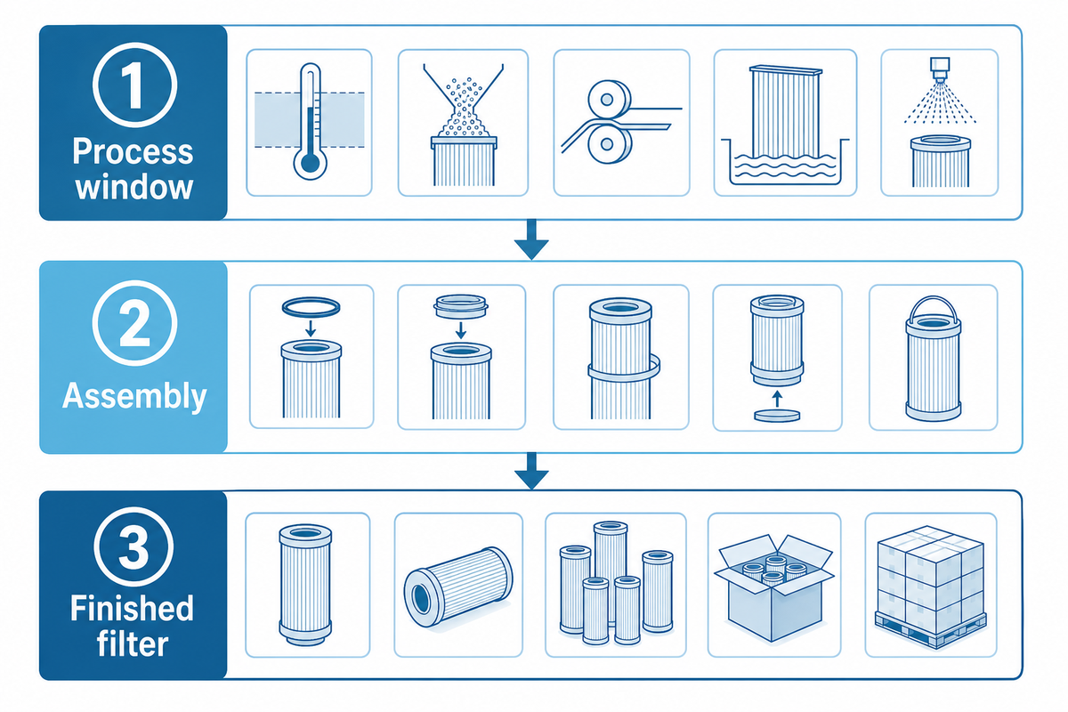
Reliable release uses three evidence layers, with each layer covering a specific area of the process. Process-window evidence checks to see if conditions have remained approved. Assembly evidence checks if joints and geometry have formed as per the qualification. Finished-filter evidence checks if the completed cartridge passes the product method. None of these three should be redefined as another.
| Layer | Question answered | Typical evidence | What it cannot prove alone |
|---|---|---|---|
| 1. Process window | Were monitored variables inside the approved operating range? | Recipe revision, temperature, energy, pressure, timing, dispense, alarms, stops | Unmonitored interface condition or finished performance |
| 2. Assembly | Did the element, seam, caps, adapters, and seals form as qualified? | Dimensions, joint checks, visual criteria, sections, displacement, retained samples | Every application claim or long-term service outcome |
| 3. Finished filter | Did the complete cartridge pass its specified release method and limit? | Raw integrity, leak, pressure, flow, or other product-test result with setup and disposition | Performance outside the method’s validated scope |
Different tests answer different questions, and their names shouldn’t be switched around. Even within one integrity method, the wetting fluid, the temperature, the stabilization time, the volume of hardware, the behavior of the instruments, and the decision limit may all be important. It was also reported that in a peer-reviewed cartridge filter study, the sensitivity of bubble-point-type defect detection depends on test conditions and defect characteristics. Therefore, in this case, the membrane context should not be considered a universal threshold.
The test system also needs a decision-criteria basis. Here, you need to consider if the calibration traceability has been established, what the limit capability is, verification of the setup, measurement uncertainty, the reason for sampling, the retest policy, and the conformity decision rule. Otherwise, a value near the limit may alternate between PASS and FAIL due to the measurement system rather than the cartridge. False acceptance of product releases a suspect product; false rejection of product creates scrap or rework. Both false-acceptance and false-rejection risks should be treated with due care.
In the filter housing of the end user, manufacturing release doesn’t cover qualification. A factory may release cartridges against an agreed drawing and test plan, but the buyer still has to assess if the cartridges work in the system. Different systems assign validation responsibilities to sterile processing, hydraulic systems, compressed air, water treatment, food contact, and general industrial filtration. Keep the claim connected to the method and responsible party.
Trace Defects Back to the Right Checkpoint
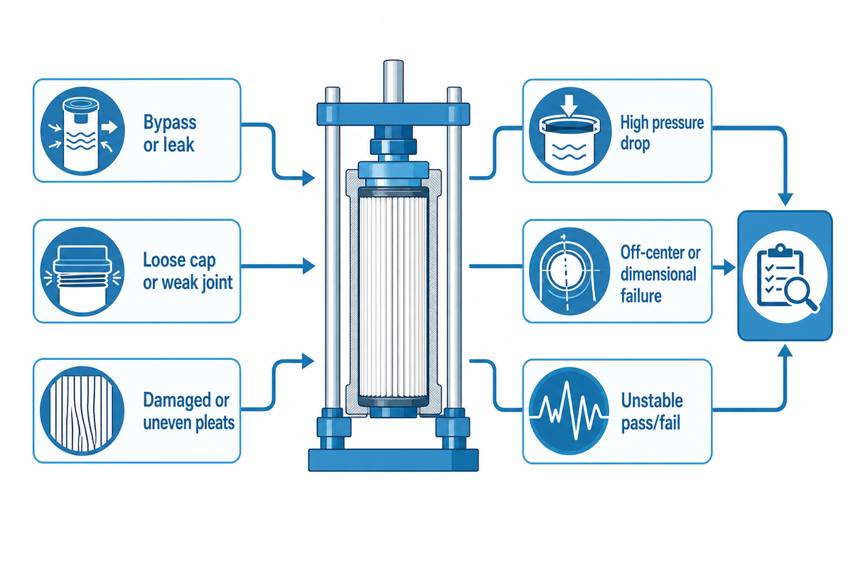
When breaking down an issue, the beginning steps are containment and evidence, not a premature recipe change. Hold suspect output, identify the affected lots and time window, verify the test system, and check defects against upstream records. Reproduce the issue under controlled conditions and change one approved factor at a time and record the results.
| Symptom | Check first | Then investigate | Unsafe shortcut |
|---|---|---|---|
| Bypass or leak | Test setup, seal condition, component identity, handling | Cap or adapter geometry, joint path, seam, seating, contamination | Increase joining energy or adhesive without locating the path |
| Loose cap or weak joint | Materials, interface cleanliness, seating, cure or cooling state | Compatibility, energy or bond window, fixture, early movement, supplier variation | Release on appearance alone |
| Damaged or uneven pleats | Incoming media, transfer, handling, first-off geometry | Tension, pleat settings, cutting, cage insertion, thermal exposure | Force the pack into an undersized cage |
| High pressure drop | Test condition, media identity, flow direction, conditioning | Pleat count and height, blocked area, adhesive intrusion, deformation | Change the limit before confirming the method |
| Off-center or dimensional failure | Gauge method, datum, component lots, fixture condition | Seating motion, tolerance stack, wear, thermal distortion | Offset the fixture to hide component variation |
| Unstable pass/fail | Instrument status, setup, environment, operator sequence | Capability, uncertainty, conditioning, decision rule, lot variation | Retest until a desired result appears |
The investigation should consider supplier variation and within-lot variation. Two lots of the same part number may have different dimensions or may have varying surface conditions or resin behavior or may have different media stiffness or other characteristics that may affect assembly. Compare retained incoming results and approved supplier evidence before changing the settings on the machine. A change of a setting to address one out-of-spec component may result in another issue when the next conforming lot is supplied.
Preserve the failed sample and all relevant raw test data. Photos can capture position, but more valuable information may be retained in samples of destructively tested sections, dimensional results, joints, test traces, and retained material. Document what changed, when it changed, who authorized it, and which output was affected. The objective isn’t just to restart the process; it’s to justify the final disposition of each suspect unit by returning the process to a controlled state.
Release Changeovers, Define Good Output, and Prepare the Equipment Brief
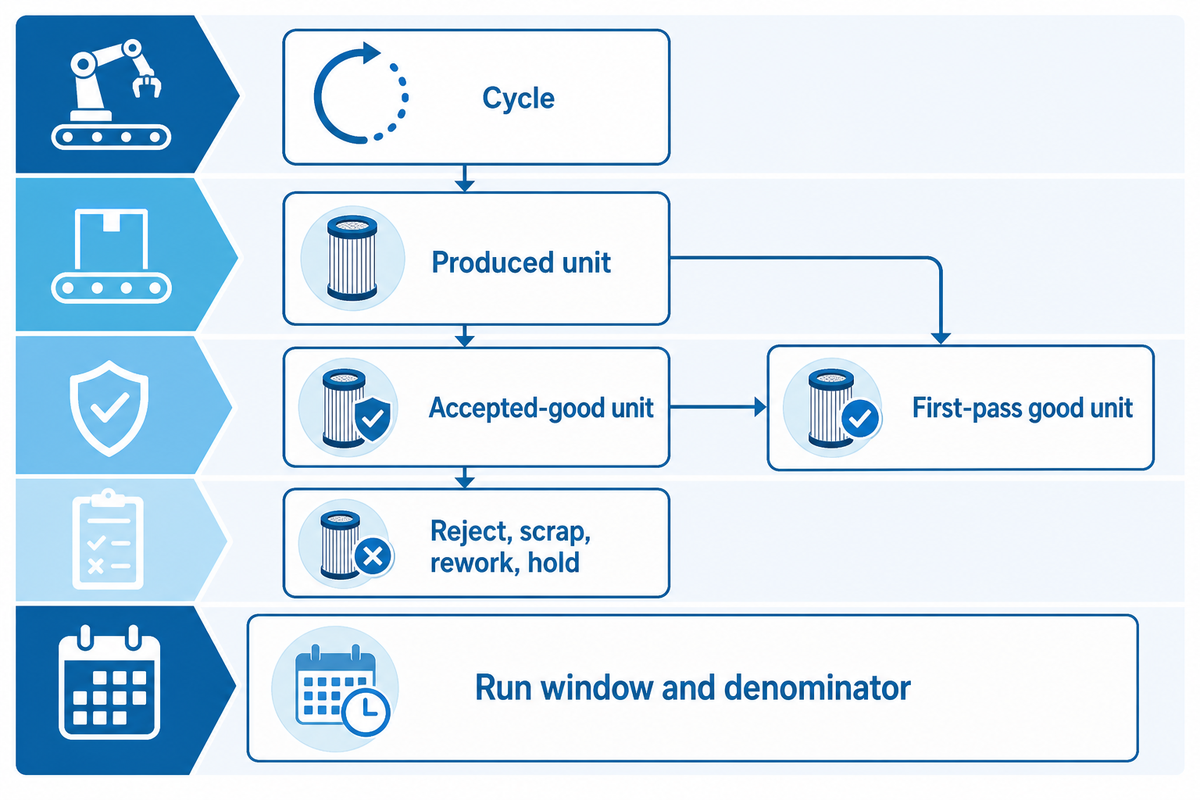
The production line is fully operational only when changeovers can return the line to a controlled state and when output metrics describe accepted cartridges and acceptance tests correspond to the actual route of the product. Communicate these requirements as a cartridge family dossier and an equipment brief prior to evaluating vendors, cycle times, and project milestones.
Release of changeover should include clearing of the line, correct materials, an approved recipe and tooling, first-off inspection, test-system verification, and authorization for commencement of serial production. Jam clearing and maintenance require a separate safety analysis. In the United States, OSHA 29 CFR 1910.147 addresses hazardous-energy control within its scope. For the actual installation, the applicable guarding, lockout and tagout, site procedures and local laws must be assessed; line clearance and first-off approval are NOT substitutes for safety.
For every project value, specify a unit and measurement basis: dimensions in mm, mass in g, pressure in kPa, flow rate in L/min, temperature in °C, cycle time in s, connected load in kW, and ratios in %. These values are representative of examples of metrics to be reported, and they aren’t absolute or universal limits for cartridge design space.
| Term | Define before the test | Common reporting error |
|---|---|---|
| Cycle | Machine sequence start/end and whether an actual cartridge was processed | Treating empty or interrupted cycles as product output |
| Produced unit | Physical unit reaching the agreed count point | Calling every produced unit saleable |
| Accepted-good unit | Unit that completed the defined checks under the conformity rule | Counting units before test or disposition is complete |
| First-pass good unit | Accepted without adjustment, repair, rework, or repeated test | Hiding intervention inside total accepted output |
| Reject, scrap, rework, hold | Mutually exclusive dispositions and authorization rules | Removing held or reworked units from the denominator |
| Run window and denominator | Start/end, planned exclusions, stops, materials, sample and total count | Quoting a peak interval as sustained good output |
FAT, FIT, SAT, and SIT should be considered contract-specific rather than widespread contract acronyms with fixed scope. FAT verifies agreed to machine functions and representative test runs at the supplier site. FIT verifies specified interfaces. SAT verifies installed operation. SIT verifies the actual process and product route at site. The contract should define samples, time period, material, instrumentation, intervention allowed, acceptance criteria, responsibilities, and deliverables for each stage.
Cartridge-Family Production Dossier
Write a single, controlled dossier for each cartridge family or justified configuration group. Include the frozen drawing, approved BOM, route and station map, recipe revision, tooling and gauge IDs, sampling plan, inspection plan, testing and inspection method, testing and inspection limits, calibration status, disposition of deviations and nonconformance, changes made and reasons, lot tracking, release of the product, and storage or packaging condition. The dossier is the handoff between design intent and reproducible manufacturing.
Requirement-First Equipment Brief
Provide the equipment supplier cartridge families and drawings, a compatibility materials matrix, service conditions, preferred and alternate routes for joining, CTQs, required inspections and tests, output definition, changeover range, traceability, utilities and safety, and expectations for documentation. For the full product-line context, refer to UDMachine’s filter cartridge making machines.
Is the process brief ready to be converted into a line configuration?
Share your drawings, materials, CTQs, joining routes, test method, accepted-good-output definition, changeovers, and integration requirements with UDMachine.
Frequently Asked Questions
Is there one standard filter cartridge assembly process?
No. The route depends on cartridge construction, media format, support components, joining method, service duty, and the evidence required at release. A pleated cartridge may need media preparation, pleating, seam joining, core and cage insertion, and end-cap bonding or welding. A melt-blown or string-wound element follows a different formation route. Use the nine stages as a control framework, not a universal machine list or mandatory standard.
What are the main stages in making a pleated filter cartridge?
The main stages are product definition, incoming-material control, media preparation, pleat-pack formation, structural assembly with the core and cage, end-cap or adapter joining, in-process approval, finished-cartridge testing, and traceable release. The station order can change with the design. Each stage should have a verified input, controlled variable, acceptance check, and retrievable record rather than relying on the final test alone.
How are filter cartridge end caps attached?
End caps may be attached by adhesive bonding, thermal or infrared joining, ultrasonic welding, spin welding, mechanical retention, or another qualified method. The choice depends on cap, media, core, and cage materials; joint geometry; cleanliness; allowable thermal load; cycle; tooling; and validation burden. A route that works for one polypropylene construction isn’t automatically suitable for a dissimilar-material or temperature-sensitive cartridge.
What quality checks are used during assembly?
Use incoming identity and dimensional checks, first-off approval, in-process recipe and geometry records, joint evidence, and a defined finished-filter test. Match each check to the failure it can detect; no single check proves every outcome.
Can a PLC PASS prove filtration performance?
No. A PLC PASS can show only that variables connected to its logic met programmed conditions. It doesn’t observe every joint interface, material property, seal surface, or handling event. It can’t prove that a weld or bond formed correctly, that the filter retained a target particle challenge, that pressure-drop behavior meets the defined method, or that the cartridge will survive its intended service. Product claims require validated finished-filter evidence with a stated setup, calibrated instrument, raw result, limit, uncertainty basis where relevant, and conformity decision rule.
What commonly causes leakage or bypass?
Potential causes include wrong or damaged components, an open media seam, contaminated joints, cap misalignment, seal damage, handling, and test-setup error. Verify the test system, contain the lot, and locate the path before changing the recipe.
What is the difference between FAT, SAT, and finished-product validation?
FAT demonstrates the functions, alarms, controls, changeovers, and representative runs agreed for the supplier site. SAT demonstrates installed operation with the defined utilities, environment, interfaces, operators, and site conditions. Finished-product validation addresses the actual cartridge route and intended claim using approved materials, equipment, methods, and limits. The project should also define whether FIT or SIT evidence is required. Passing FAT doesn’t qualify a buyer’s cartridge, prove the installed line is integrated, or replace application validation. Scope, samples, interventions, instruments, responsibilities, and records must be agreed before each test.
What should be sent to an assembly-equipment supplier?
Send controlled drawings, materials, service conditions, CTQs, joining options, tests, accepted-output definitions, variants, utilities, traceability, safety constraints, and required records. State unknowns openly and include representative parts where possible.
About UDMachine
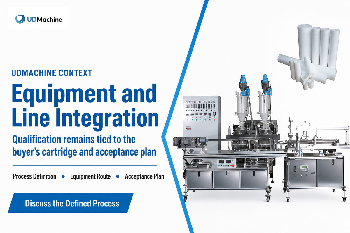
Suzhou UDTECH Technology Co., Ltd., operating as UDMachine, supplies filter-cartridge production equipment and line-integration support. Company identity is kept separate from validation claims because assuming a supplier profile proves suitability creates a release risk: the assembly route must still be confirmed against the buyer’s cartridge, materials, service conditions, applicable requirements, and acceptance plan.
References & Sources
- U.S. FDA, Process Validation: General Principles and Practices (used only within the scope stated in the guide).
- ISO 2942:2018, Hydraulic fluid power filter elements, fabrication integrity and first bubble point
- ISO 16889:2022, Hydraulic fluid power filters, multi-pass performance evaluation.
- TWI, Ultrasonic Welding of Injection Moulded Components: Component Design and Weld Parameters.
- OSHA, 29 CFR 1910.147, Control of Hazardous Energy (U.S. jurisdiction and scope only).
- Peer-reviewed study, Defect Detection Sensitivity of Bubble-Point-Type Tests for Sterilizing-Grade Membrane Cartridge Filters.
- U.S. Patent US6315130B1, Filter cartridge construction example (design context, not an acceptance standard).