Get in touch with Suzhou UDTECH Technology Co., Ltd. Company

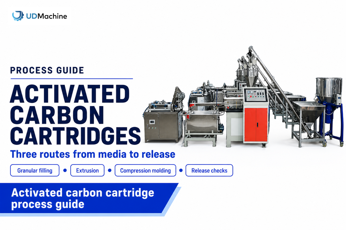
The activated carbon filter cartridge manufacturing process starts with approved carbon, follows a filling or block-forming route, and is completed with cartridge assembly and release checks. The purchase of activated media usually puts the carbonization and activation outside the cartridge factory’s scope.
A loose granular cartridge or a bonded carbon block may fit into the same housing, but may require different equipment. Starting with the construction drawing, follow the material through every handoff and ensure that there’s an agreed release record for the assembled cartridge, not just the carbon body.
Process at a glance
- Loose granules: prepare the shell, dose media, retain particles and close.
- Extruded block: blend carbon and binder, extrude, cool and cut.
- Molded block: charge individual molds, heat and consolidate, cool and demold.
- All routes: finish the cartridge, verify the intended claim and preserve lot identity.
Where the activated carbon cartridge process begins
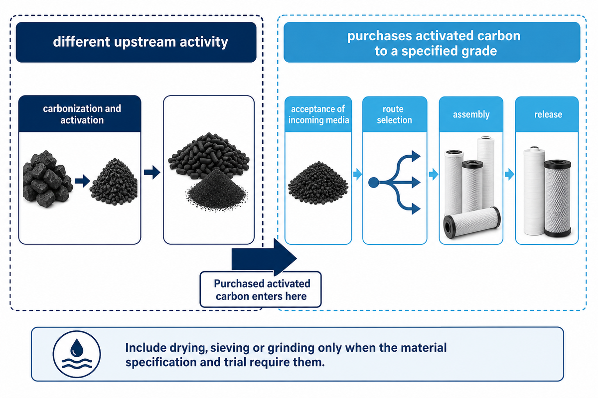
The manufacture of cartridges starts at the acceptance of incoming media when the factory purchases activated carbon to a specified grade. Making that carbon from a carbonaceous feedstock is a different upstream activity. The purchasing boundary determines whether cartridge-forming equipment or a completely different carbon-production facility is required.
A KX Industries production account by Evan Koslow describes the receipt of activated carbon before grinding, classification, blending and extrusion. It is a useful sequence, not a requirement to grind every supplied grade. Carbon already delivered to qualified size distribution may enter a different preparation sequence.
Carbon produced from carbonaceous feedstock has already undergone its supplier’s activation process. Thus, the manufacturing of a cartridge with it is a different scope from a method for manufacturing activated carbon. Be clear about this purchasing boundary when ordering a block filter for water treatment.
Common scope mistake: specifying an activation furnace because the finished product contains activated charcoal. First confirm if raw material is already activated, graded and accepted. Drying, sieving, or other conditioning should be included in the route only if the material specification and trials warrant it.
How to manufacture an activated carbon filter?
To manufacture an activated carbon filter cartridge, approve the media and cartridge drawing, choose granular filling or bonded-block forming, complete the shell or end-cap assembly, and test the finished design. Establish the required water-treatment claim before selecting a production process, since shape and appearance can’t verify contaminant removal.
For each operation state the output, i.e. prepared blend, bare block, wrapped body, joined cartridge or packaged product. These names support equipment quotations and comparisons. They also ensure that a supplier’s forming cycle figure won’t be mistakenly viewed as the rate of accepted finished cartridges. Manufacturing activated carbon block filters is completed only at the deliverable named in the order.
Three manufacturing routes for carbon filter cartridges
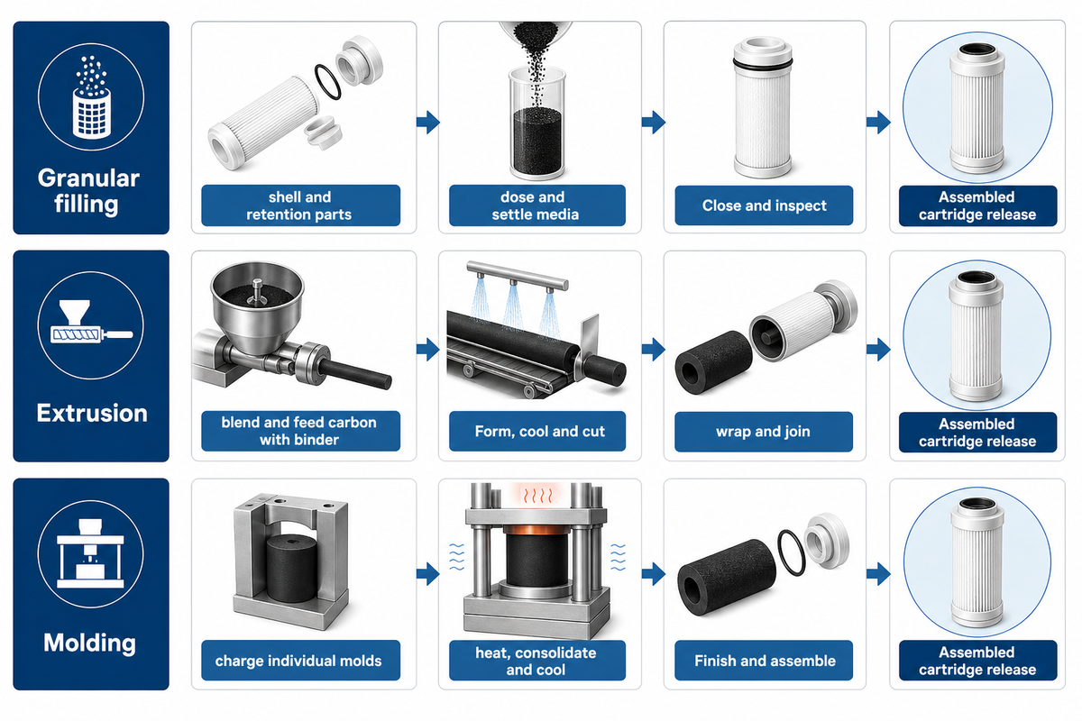
There are three common cartridge routes where the point of divergence is when carbon is retained as a medium or bonded as a body. Granular filling places media in a shell. Extrusion produces a continuous porous profile. Compression molding forms individual bodies. Downstream assembly depends on the chosen construction rather than the word “carbon” alone.
Use the 3-Route Carbon to Cartridge Hand-off Map below to assign the next operation. It’s an editorial planning aid, not a production standard. The block-forming distinction follows Michael D. Steinhardt’s carbon-block manufacturing explanation.
| Route | Operation | Handoff record | Limitations / Not suitable for |
|---|---|---|---|
| Granular filling | Accept shell and retention parts | Drawing, fit and material identity | Tube dimensions alone do not define media retention |
| Granular filling | Dose and settle media as specified | Carbon lot, fill mass and fill condition | No universal tamping setting for every shell |
| Granular filling | Close and inspect | Closure, particle retention and flow path | Does not create a bonded block |
| Extrusion | Blend and feed carbon/binder | Blend identity and feed record | A published patent recipe is not a validated factory recipe |
| Extrusion | Form, cool and cut | Time position, dimensions and body condition | Bare-block output excludes assembly rejects |
| Extrusion | Wrap and join as drawn | Body-to-cartridge identity and interface checks | Wrapping cannot repair an unsuitable body |
| Molding | Charge individual molds | Charge identity and mold/cavity reference | Charge weight alone does not prove uniform density |
| Molding | Heat, consolidate and cool | Cycle history and demold condition | Settings depend on material and geometry |
| Molding | Finish and assemble | Cavity-linked finished sample and test record | One accepted cavity does not establish every cavity’s result |
Let’s imagine a buyer with two drawings. One shows loose activated carbon granules retained between screens. The other drawing shows a self-supporting porous cylinder. Both are referred to as carbon cartridges in the inquiry. An extrusion-only quotation addresses the second body, but doesn’t address the first cartridge’s dosing and retention functions. The buyer should split the drawings, name the output at each quoted station and ask what operations remain outside the offer. This is a construction decision, prior to a capacity decision. A historical CR4 discussion similarly distinguishes rolled carbon felt from bonded blocks; the shared cylindrical shape is not enough to select machinery.
Activated carbon and binder: specify the material system
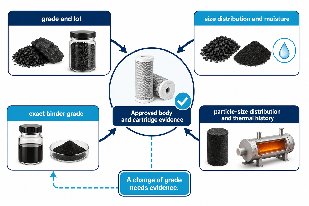
The forming behavior of a carbon block, in conjunction with adsorption requirements, affects the resulting porous body. Factors including powdered activated carbon properties, binder grade, particle-size distribution and thermal history influence the formation of the porous body. Specify the material system used in the supplier’s trial, and maintain its identity throughout production. Change of grade needs evidence rather than a simple name change.
The activated carbon used in the trial must be traceable to its grade and lot. Record the size distribution of activated carbon powder rather than relying on a mesh name. For carbon cartridge filters, the moisture content of the activated carbon is another preparation variable to define. If the approved process specifies that activated carbon is dried before blending, preserve that condition in the production record.
The paper by Braslavska and colleagues describes the difficulty of binding particles while retaining useful porosity. Separately, Lim and colleagues in 2010, studied the carbon-LDPE honeycomb and observed material-dependent surface area and proposed binder pore blocking as an explanation. However, their work doesn’t provide a drinking-water cartridge recipe.
| Input | Record | Why retain it? |
|---|---|---|
| Activated carbon | Supplier, grade, lot and relevant adsorption data | Nominally similar media can have different service behavior |
| Particle distribution | Agreed method and acceptable distribution | Mesh labels alone do not describe every fraction |
| Polyethylene binder | Exact resin grade and supplier processing guidance | Polyethylene grades are not interchangeable by name |
| Conditioning | Moisture requirement and any qualified drying step | Unrecorded preparation makes trials hard to reproduce |
| Water-contact parts | Material identity and supporting documentation | Carbon activity does not establish every component’s suitability |
What is activated carbon and why is it used in cartridge filters?
Activated carbon is a highly porous form of carbon used to adsorb selected substances onto its internal surface. In a cartridge, accessible carbon surface provides contact with flowing water, while the cartridge construction controls the flow path. Adsorption and mechanical capture are separate functions, even when one filter performs both.
Pores in the structure of activated carbon provide sites for adsorption. Accessible activated carbon surface matters after forming, not just before adding binder. Impurities adsorbed on the surface of activated carbon use finite capacity, and a water quality claim therefore requires a specified end point.
The Purdue-hosted extension explanation makes the useful boundary clear: carbon can’t remove all drinking water contaminants. Performance depends on the target impurity, water conditions and contact with the media. More surface area per gram, therefore, isn’t proof of a cartridge’s finished service life. Maintain the intended organic contaminants, chlorine claim, or water taste and odor purpose in the trial specification. The efficiency of activated carbon must be asserted against that particular claim.
Copying a binder percent from Google Patents and saying it’s UDTECH’s process isn’t permissible. WO2017086763A1 is a published patent application naming the inventor and assignee; this isn’t evidence UDTECH owns the invention or that it’s a universal manufacturing method.
Granular activated carbon: filling and retention
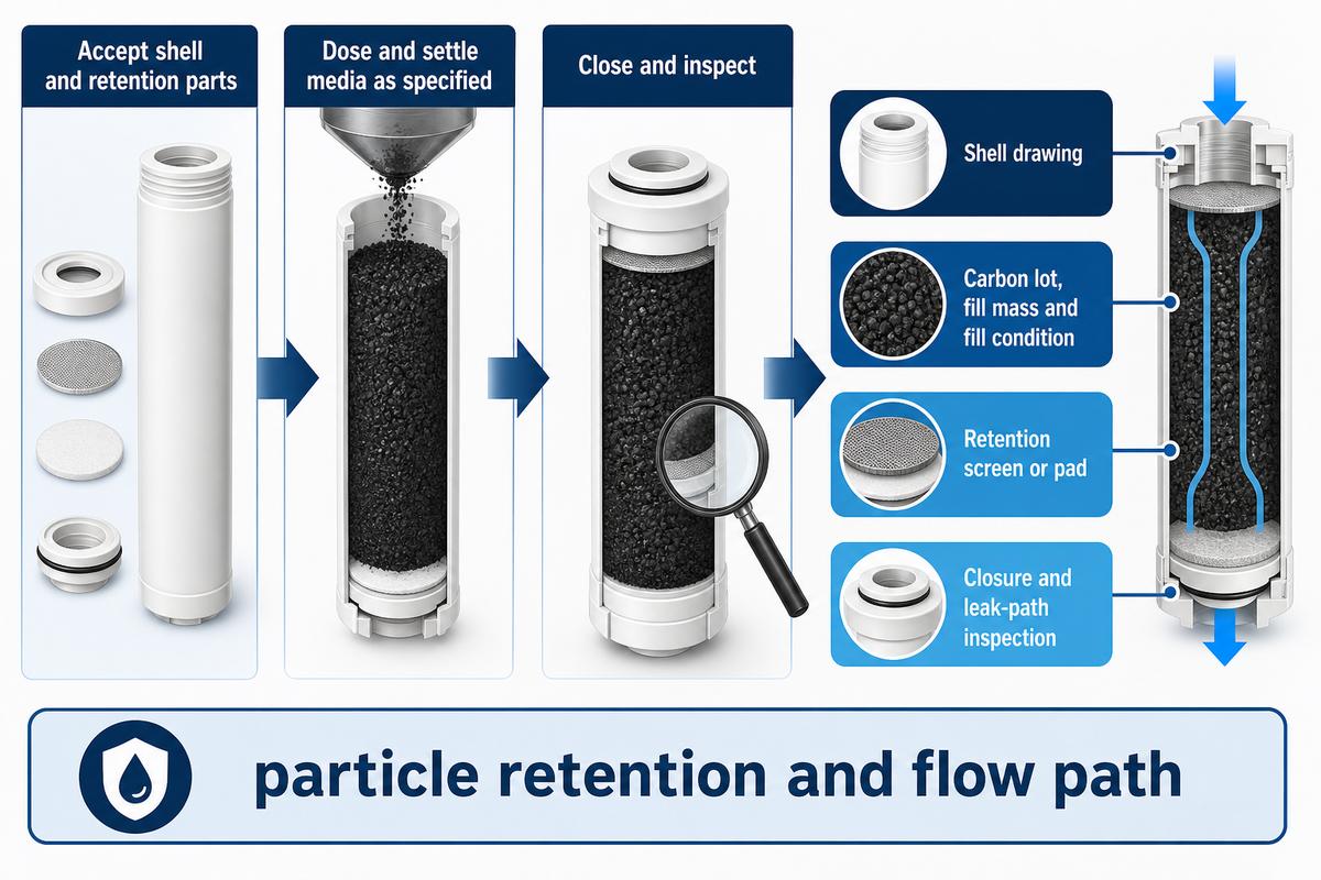
Granular activated carbon cartridges retain filter media within a designed water flow path. The focus, therefore, is on the controlled dosing of the shell, the specified method of settling, retention layers and closure. The assembly must keep the media in place and allow the water to flow through the bed under the operating conditions for which it’s designed.
The loose-fill route doesn’t produce activated carbon block material. It does require a drawing identifying screens, pads, caps and seals. Carbon lots and fill masses are recorded and the filled condition is assessed. Closure is checked as well as particle retention. A nominally full shell can still have an unintended flow path. Carbon filtration depends on contact with the media, so using activated carbon in a shell is not enough if water can pass around it.
UDTECH’s UDF tube-making machine illustrates a frequent scope distinction: manufacturing the plastic tube doesn’t establish that media filling, retention-part insertion and final closure are included. Ask for those functions separately. An activated carbon filtration assembly needs its complete flow path defined.
Don’t presume that vibration or compression are required due to another granular activated carbon process using them. The design of the shell, the retention system and the granulated activated carbon grade determine what’s required. It’s best to test the actual assembly. Inspect the condition after handling and just after filling. A record of filling supports the consistency of the process; it isn’t a substitute for a water-filtration test.
Carbon block forming: extrusion and compression molding
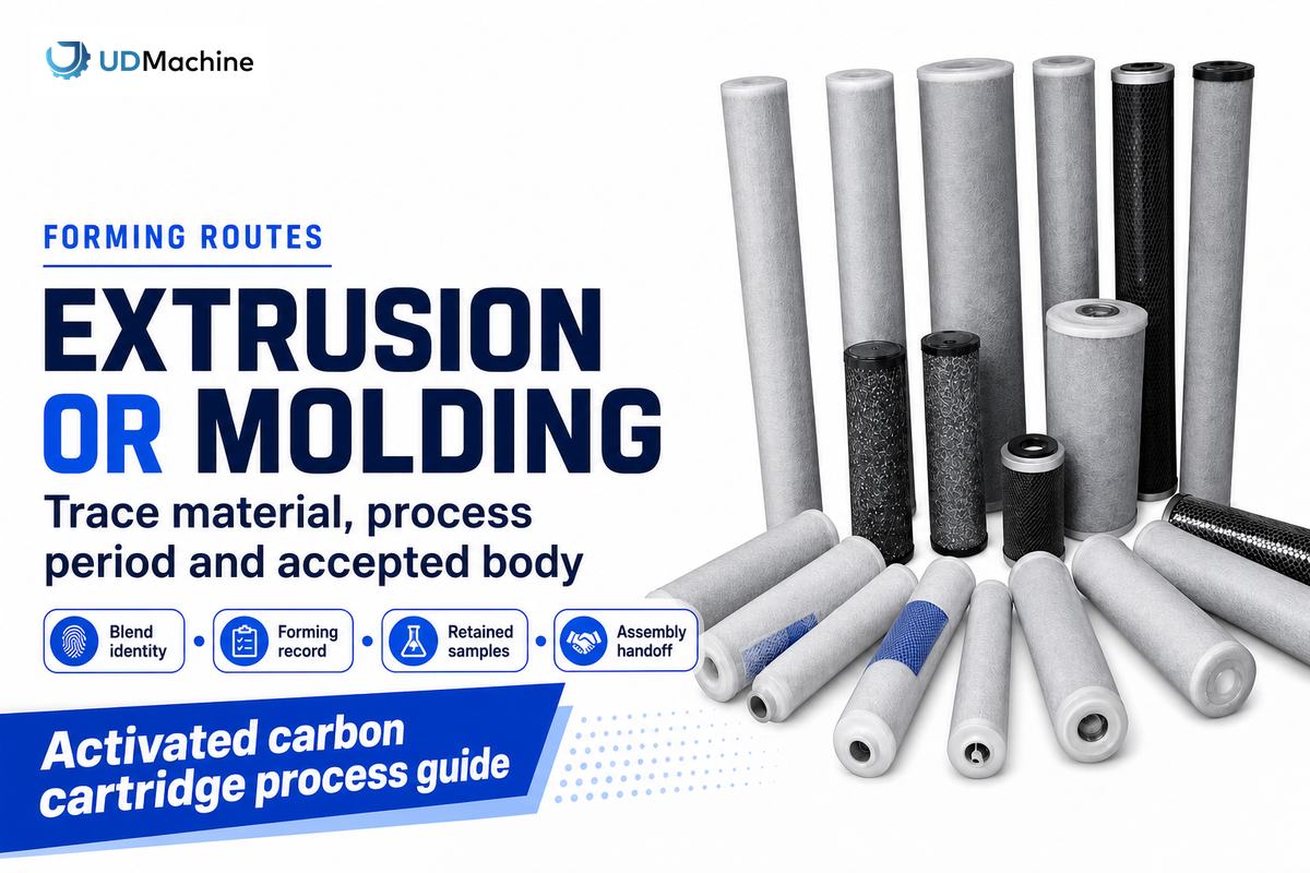
Extrusion and compression molding bond activated carbon particles into a porous body using a qualified material and thermal process. An extruder forms a continuous profile that’s cooled and cut. Individual molds produce bodies through charging, heating, consolidation, cooling and removal. Each process needs to sample to account for variation.
In extrusion, provide the prepared blend, feed condition and operating history with sample time. Initial startup pieces and stable run pieces provide different information. The bodies must be cooled and cut, leaving a part which can pass to the finishing process without confusing temporary softness or handling marks with the final condition of the part.
Molding changes the sample map. Identify the mold or cavity and compare the charge and cycle for each retained body. Analyzing anonymous finished pieces provides no way to locate variations. Neither route gives every carbon – binder combination the same process window, and a machine setpoint isn’t a measurement of the part. A carbon block filter for water should be qualified in its intended assembly, even when its porous activated carbon body looks sound.
Imagine a factory qualifying a new carbon lot while keeping the binder grade constant. The first block looks good, and the operator wants to release the whole run. A better approach is to retain labeled start-up and subsequent samples; qualify the carbon lot; and compare the accepted dimensions, hydraulic response and planned performance checks. In the case of an unexpected result, the team knows which material and process period produced the result. This example has no made up yield or removal percentage. It illustrates the concept why a good-looking block is a sample and not a release decision. For station controls and machine specific checks use the other CTO cartridge machine guide.
When not to buy an extrusion-only line
Don’t use an extrusion only line when the required product is a loose granular cartridge, when the accepted deliverable includes unquoted downstream assembly, or when the proposed trial is unable to use your specified materials. These are scope mismatches which more forming speed won’t resolve.
In its published CTO, UDTECH describes a configuration with an inner diameter in the 9-100 mm range and an outer diameter in the 29-150 mm range. Those ranges don’t prove that all combinations of lengths, binders and quality targets are qualified. The same page gives a 50–60 second cycle for its stated 10-inch example; it isn’t a verified rate of packed, accepted cartridges. Use the actual drawing and material lot in the trial and determine whether the output is measured with respect to wrapping, joining, testing and/or rejecting. In the absence of those conditions, keep the quotation open until its scope is defined.
From a carbon body to an assembled cartridge
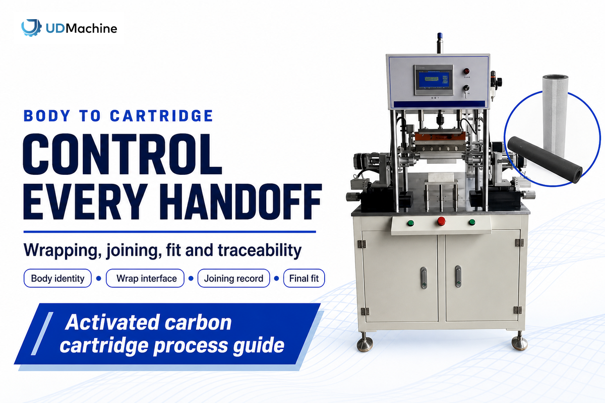
A formed carbon body becomes a cartridge only after specific finishing operations and assembly. Depending on the design, these may include trimming, pre-filter wrapping, netting, end-cap joining and seals. Keep the body’s identity during assembly in order to trace a failed sample to the relevant interface.
Wrapping and joining have separate acceptance criteria. The carbon-block wrapping equipment must accept a stable body and leave the required cap-seat clearance. The end-cap joining equipment must be appropriate for the actual cap, body and design of joining. A page title isn’t evidence for a particular adhesive metering system.
“even the smallest size difference could allow water to go around the cartridge rather than through it”
The paired body-to-cartridge release worksheet keeps the assembly question visible. Quality teams can identify samples; Production teams can locate the handoff; Procurement and finance teams can see if a quotation stops at bare bodies.
| Record field | Illustrative entry or attachment | Decision supported | Limitations / Not suitable for |
|---|---|---|---|
| Body identity | CB-A / E-start | Connect a body to its forming period | Identifier is not a measurement |
| Material identity | Actual carbon and binder lot records | Confirm trial materials match the order | A grade name alone does not identify the lot |
| Sampling position | Startup, stable period or mold/cavity reference | Locate variation within the run | No universal sampling frequency is prescribed |
| Body measurements | Results against the approved drawing | Accept the body for assembly | Cannot establish finished-cartridge fit |
| Wrap interface | Wrap lot and observed cap-seat clearance | Check the downstream interface | Does not establish adsorption capacity |
| Joining identity | J-A / named cap lot and joining record | Pair the final cartridge with its body | Process record does not replace final checks |
| Final fit | Specified housing/interface check | Evaluate intended flow-path integrity | No generic pressure limit is implied |
| Hydraulic result | Flow, conditioning and pressure-drop record | Compare like-for-like assemblies | Different conditions invalidate a direct comparison |
| Claim-specific result | Product identity, test method and endpoint | Support the intended treatment claim | Does not extend to untested contaminants |
| Disposition | Pending / accepted / held, with responsible owner | Document the actual release decision | Blank attachments cannot support release |
These labels are worked examples, not UDTECH test results. The worksheet organizes evidence; the product owner still defines valid methods and acceptance criteria. The filter cartridge assembly guide elaborates on the downstream sequence.
Release checks for filtration and cartridge quality
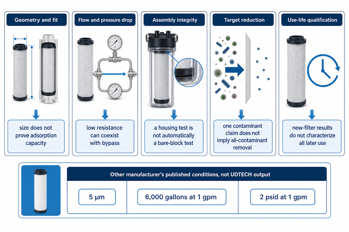
Carbon cartridge release requires evidence matching the question being asked. Dimensions establish fit, hydraulic checks describe resistance under specified conditions, and integrity checks address the intended assembly. Reduction of Contaminant requires its own evidence. A favorable result in one category can’t replace the others.
Compare treated water and raw water against the agreed challenge conditions. Higher flow rates cannot be assumed to preserve the same removal result. A proposed method for removing a substance must identify its endpoint; using carbon does not itself establish that endpoint or prove how long the filters work.
| Check | Record with the result | Limit |
|---|---|---|
| Geometry and fit | Drawing revision, method and measured dimensions | Correct size does not establish adsorption capacity |
| Flow and pressure drop | Flow rate, water condition, conditioning and assembly | Low resistance can coexist with an unintended bypass |
| Assembly integrity | Method suitable for the body, seal and housing design | A housing pressure test is not automatically a bare-block test |
| Target reduction | Challenge, flow, endpoint and product identity | One contaminant claim does not imply all-contaminant removal |
| Use-life qualification | Intended service and stagnation conditions | New-filter results alone do not characterize all later use |
For example, the Hydronix CB-25-1005 product table shows a nominal 5 µm rating, 6,000 gallons at 1 gpm chlorine capacity, and an initial pressure drop of 2 psid at 1 gpm. These are that model’s published conditions, not UDTECH output conditions. Removing the flow condition would make the figures less useful for comparison.
Hydronix makes the same distinction between material-only component certification and performance testing on the same page. Following the stated product and claim as NSF’s standards guide describes is advisable. A company’s quality assurance certificate or machinery documentation doesn’t prove the finished cartridge reduces contaminants.
Conditions of service are important past initial release. Jakpa and Alfredo’s 2024 study abstract reports on microbial changes with stagnation and disinfectant switching in three laboratory carbon-block filters. That bounded result supports including intended-use conditions in qualification; it does not establish a universal failure rate. For hydraulic interpretation, see the cartridge pressure-drop guide.
Industry Outlook: standards and supplier trials
Changes in testing requirements make the intended product claim a better starting point than a generic claim to improve filtration. In a new cartridge project, tie the current claim-specific testing to the supplier testing before finalizing equipment scope. Otherwise, a successful forming demonstration may leave the decisive qualification work unresolved.
ANSI’s public account of NSF/ANSI 53-2025 identifies changes involving PFAS testing and lead sampling. These are typical test planning changes and are not evidence that a new carbon-forming method has displaced extrusion or molding. Ask the relevant lab which edition, claim and procedure apply to the product in question.
Integration, utilities and the supplier trial brief
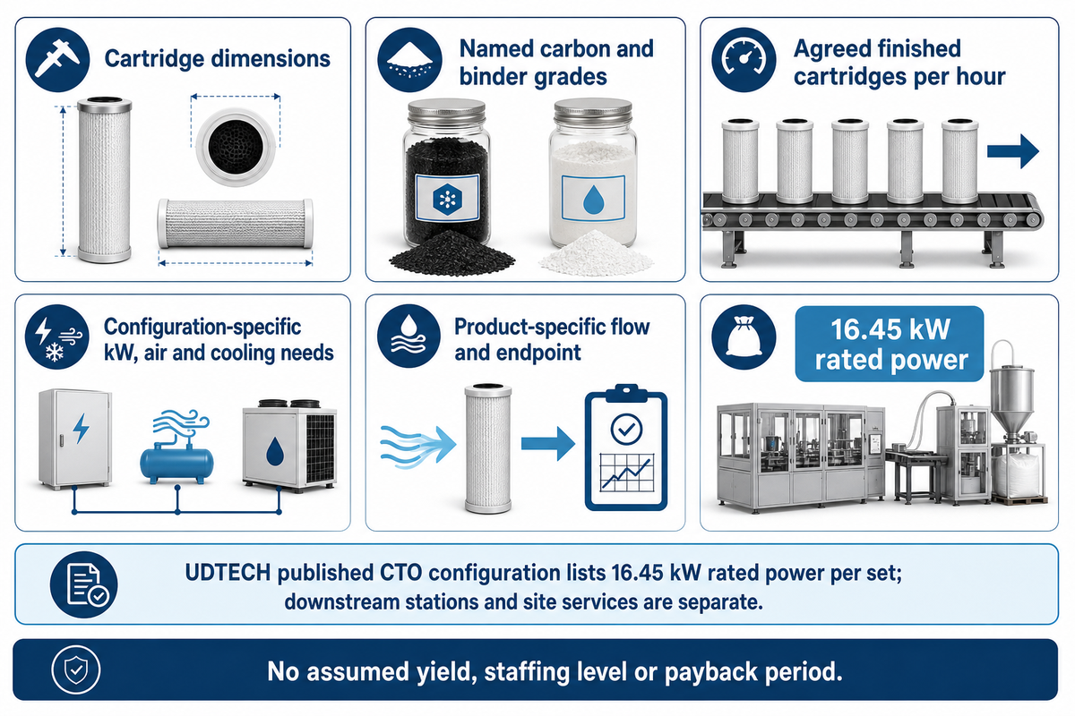
UDTECH’s published CTO forming configuration lists 16.45 kW rated power. Treat that as a named machine figure. Downstream stations, cooling, compressed air and extraction need their own stated loads and responsibilities. Don’t convert it into a total-factory energy promise.
In a hypothetical quotation review, procurement receives an attractive forming-machine price while quality expects packed cartridges and finance budgets only the listed machine power. The scope sheet defines each downstream operation (included, optional or excluded); utility connections; who supplies the trial materials; and how the accepted output is to be measured. Quality then fixes the product specific test plan to the revision of the drawing. Those yield, staffing and payback values belong to the agreed configuration and a measured trial. Nothing in this example assumes a yield, staffing level or payback period. The aim of the purchasing activity is to obtain a comparable offer with responsibilities attached, rather than an impressive unqualified cycle figure.
Powder handling also requires a delineated facility boundary. OSHA’s combustible-dust guidance explains that particle size, shape and moisture can impact the hazards associated with powders. Someone is to be responsible to assess the actual powder and design the facility. A dust collector, for example, doesn’t scope this work.
Copy the following questions into your inquiry, replacing drawing-dependent entries with your own requirements.
RFQ checklist — copy these into your quote request:
| Parameter | Recommended range | Why it matters | How to verify |
|---|---|---|---|
| Cartridge dimensions | Drawing-defined mm and tolerances | Sets body and assembly interfaces | Trial with approved drawing |
| Accepted output | Agreed finished cartridges per hour | Separates forming rate from shipped output | Timed trial including stated rejects |
| Material system | Named carbon and binder grades | Keeps the trial relevant | Lot records and retained samples |
| Utilities | Configuration-specific kW, air and cooling needs | Prevents omitted site costs | Supplier load and connection schedule |
| Performance claim | Product-specific flow and endpoint | Defines what acceptance means | Agreed laboratory procedure |
Suzhou UDTECH Technology Co., Ltd. supplies filter-production machinery. Send the drawing and this scope sheet when discussing a filter cartridge production line, in order to negotiate forming, assembly and testing.
Frequently asked questions
How many microns should a carbon water filter be?
Choose the rating for the intended duty and test method.
A micron label describes a particle-related rating, not the full adsorption performance of a carbon cartridge. Decide whether the rating is nominal or absolute, what test supports it, and which flow condition applies. The required chlorine or organic-compound reduction needs separate evidence. Carbon particle size and the finished filter rating shouldn’t be treated as interchangeable measurements.
Where are activated carbon filters used?
Common uses include selected taste, odor and contaminant-reduction duties.
Carbon filters are used in drinking water treatment where the chosen medium and cartridge can meet a stated purpose. Different grades of activated carbon are used for different duties. A cartridge for water purification, an industrial process filter and a gas-service adsorber need different qualification. Start with the fluid, target substances, flow and service conditions. Don’t transfer a compressed-air product’s published performance to a water purifier simply because both contain carbon.
What are the disadvantages of an activated carbon filter?
Capacity is finite, and performance depends on the application.
An activated carbon filter doesn’t remove every dissolved substance or establish safe drinking water by itself. Adsorption capacity can be exhausted without an obvious drop in flow, while particulate loading can raise resistance. Fit, bypass and the manufacturer’s replacement instructions also matter. Evaluate the specified product and intended water supply instead of treating carbon as a universal purification process.
Does manufacturing a cartridge include activating the carbon?
Usually not when the factory buys qualified activated media.
Upstream activation and downstream cartridge fabrication are separate project scopes. The cartridge plant may still need material conditioning, forming or filling, and assembly. Confirm the delivered carbon grade and preparation requirements before choosing equipment.
How should a factory approve a new binder or carbon lot?
Use a controlled, traceable trial against the existing acceptance plan.
Identify the changed material and keep the comparison conditions recorded. Retain representative body and assembled-cartridge samples, including relevant time positions or mold references. Compare the agreed geometry, hydraulic response, assembly condition and intended performance measures. A supplier certificate can document the input, but it doesn’t establish the finished cartridge result. If the change affects the listed product or treatment claim, involve the responsible product owner and laboratory before routine release. Record the approval decision with the material identity.
Can a cartridge line make the plastic housing too?
Only if that manufacturing scope is explicitly included.
A tube-forming machine, cartridge assembly station and pressure-containing housing process are different deliverables. Ask which parts arrive ready-made and which are produced on the quoted line. Match the answer to the actual drawing.
What is sediment filtration, and where does it fit?
Sediment filtration captures particles rather than relying on adsorption.
A sediment stage may protect or complement a carbon stage, depending on the water and system design. Mechanical capture addresses particles; adsorption addresses selected substances through interaction with the carbon surface. Wrapping a carbon block with prefilter material also creates an assembly interface that needs control. Specify the sediment duty, intended flow and maintenance arrangement instead of assuming every carbon cartridge needs the same layer. The correct arrangement follows the tested system, including the volume of water and loading expected during service.
Key takeaway
Choose the cartridge construction first. Then connect material identity, route-specific forming or filling, downstream assembly and the actual product claim in one traceable trial.
Plan the complete cartridge process
Share your cartridge drawing, carbon grade, target output and intended test requirements with UDTECH.
References and sources
- Braslavska et al., Production Technology and Filtering Properties of Carbon Block Cartridges.
- Michael D. Steinhardt, Carbon Block Manufacturing.
- NSF, Changing Water Filters and filtration standards guide.
- ANSI, NSF/ANSI 53-2025 changes.
- Jakpa and Alfredo, 2024, chlorine conversion and activated-carbon-block filters public abstract.
- OSHA, Hazard Communication Guidance for Combustible Dusts advisory publication.